


F-120 F-120
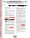
TRIGGER CIRCUIT AND WIRING HARNESS TEST (continued)
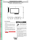
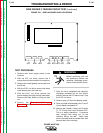
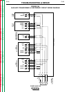
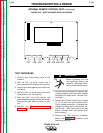
FIGURE F.43 - PROTECTION BOARD PLUG/HEADER LOCATIONS
3
1
16
1
14
1
6
1
6
1
14
1
6
1 1 1
1
4
4
4
4
11
4 7 2
PROTECTION BD
J30 J31 J32 J33 J34 J35
J36
J37
J38
J39
TROUBLESHOOTING & REPAIR
TEST PROCEDURE
1. Remove main input supply power to the
machine.
2. With the 3/8" nut driver, remove the 4
screws that hold the handle to the machine.
3. Remove the rubber gasket (cover seal) from
the lift bail.
4. With the 5/16" nut driver, remove the sheet
metal screws from the case top.
5. With the 5/16" nut driver, remove the
screws holding the right and left case sides.
Remove the case sides by lifting up and
out.
6. Perform the Capacitor Discharge
Procedure described earlier in this section
of the manual.
Before continuing with the
test procedure, perform the
capacitor discharge proce-
dure to avoid electric shock.
7. After you have completed the capacitor dis-
charge procedure for all four switch boards,
remove the PC board cover. Use the 5/16"
nut driver.
8. Remove plugs J34, J37, and J38 from the
protection board. See Figure F.1 for loca-
tion. Continue with the following checks:
NOTE: Do not remove plug J33 from the pro-
tection board.
A. With the volt/ohmmeter, check for continu-
ity between J37 - pin 1 and J37 - pin 4 of
header J37. There should be no continuity.
B. Connect a jumper between J34 - pin 11
and J34 - pin 14 of header J34 of the pro-
tection board. This simulates the closing of
the trigger on wire feeder 1 or the remote.
C. With the volt/ohmmeter, check for continu-
ity again between J37 - pin 1 and J37 - pin
4 of header J37. There should be continu-
ity now. Remove the jumper.
D. With the volt/ohmmeter, check for continu-
ity between J37 - pin 2 and J37 - pin 3 of
header J37. There should be no continuity.
E. Connect a jumper between J34 - pin 4 and
J34 - pin 7 of header J34 on the protection
board. This simulates the closing of the
trigger on wire feeder 2.
F. With the volt/ohmmeter, check for continu-
ity again between J37 - pin 2 and J37 - pin
3 of header J37. There should be continu-
ity now. Remove the jumper and connect
plugs J34, J37, and J38 back into the pro-
tection board.
If the continuity tests above detect a fault,
replace the protection board.
9. Remove plug J37 from the protection
board and inspect its pins and leads.
Make sure that the TRIG 1, TRIG 2, and
COMMON pins of plug J37 are not short-
ed together (pins 1, 2, 3, 4, respectively).
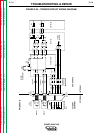
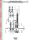
Make sure that leads #371, #372, #373,
and #374 are not exposed. See the
Auxiliary Transformer #1 Secondary
Circuit Wiring Diagram, Figure F.44.
10. Connect plug J37 to the Protection board.
If you found no problem with plug J37 pins
and leads, replace the display board.
11. After the tests are completed and the
problem successfully repaired, reconnect
all plugs to their respective boards.
Replace the PC board cover with the two
sheet metal screws.
12. Install the machine case sides and top.
13. Install the handle and the lift bail rubber
gasket.
POWER WAVE 450
Return to Section TOC Return to Section TOC Return to Section TOC Return to Section TOC
Return to Master TOC Return to Master TOC Return to Master TOC Return to Master TOC
WARNING