


F-137 F-137
LCD DISPLAY TEST (continued)
TROUBLESHOOTING & REPAIR
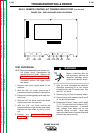
ELECTRIC SHOCK
can kill.
With input power ON, there
are high voltages inside the
machine. Do not reach into the machine or
touch any internal part.
10. Turn input power ON.
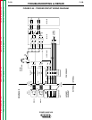
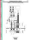
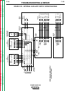
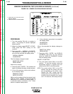
11. With the volt/ohmmeter, check the follow-
ing voltages between plug J16 pins at the
display board (without removing plug J16
from the display board):
+5 VDC Between J16 - pin 2 and J16 -
pin 3
+15 VDC Between J16 - pin 10 and J16
- pin 7
+5 VDC Between J16 - pin 1 and J16 -
pin 7
-5 VDC Between J16 - pin 9 and J16 -
pin 7
-8 VDC Between J16 - pin 6 and J16 -
pin 7
12. Turn power switch SW1 to the OFF posi-
tion and disconnect input power to the
machine. Connect plug J30 into the pro-
tection board. Connect the five leads to
the main contactor.
If the voltages checked in step 11 were cor-
rect, go to step 14.
If any of the voltages in step 11 were not cor-
rect, go to step 13.
13. Perform the following tests to locate the
problem: Auxiliary Transformer 1 Test
and Internal and Auxiliary Voltage
Supply Test. If these tests show no com-
ponent failures, go to step 14.
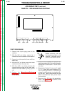
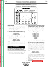
14. Make sure plug J19 is plugged into the
display board securely and that none of its
pins are loose or broken. If the pins are all
okay, replace the LCD display.
15. If the problem persists after replacing the
LCD display, replace the display board.
16. After the problem has be repaired, install
the machine case sides and top. Install
the handle and the lift bail rubber gasket.
POWER WAVE 450
Return to Section TOC Return to Section TOC Return to Section TOC Return to Section TOC
Return to Master TOC Return to Master TOC Return to Master TOC Return to Master TOC
WARNING