


F-173 F-173
INPUT RECTIFIER REMOVAL AND REPLACEMENT (continued)
TROUBLESHOOTING & REPAIR
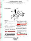
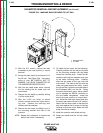
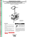
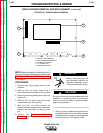
10. With the 5 mm Allen wrench and the 10
mm open end wrench, remove the two
screws mounting the input rectifier to the
heat sink panel.
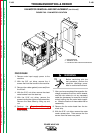
11. When replacing the input rectifier, apply a
thin, even coating of Dow Corning 340
Joint Compound (Lincoln T12837) to the
mating surfaces between the input rectifi-
er and the heat sink panel. Avoid applying
the compound to either the mounting
holes or the mounting hardware.
12. Mount the input rectifier to the heat sink
panel and tighten the two mounting
screws with the 5 mm Allen wrench and
the 10 mm open end wrench. Be sure to
tighten the screws evenly.
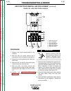
13. With the Phillips head screw driver, attach
the positive (+) and negative (-) leads to
the input rectifier. Attach the three heavy
leads and the M.O.V. assembly to the
input rectifier. Replace the M.O.V. assem-
bly if it appears damaged.
14. Apply silicone sealant to the M.O.V.
assembly connections.
15. Install the machine case sides and top.
16. Install the handle and the lift bail rubber
gasket.
POWER WAVE 450
Return to Section TOC Return to Section TOC Return to Section TOC Return to Section TOC
Return to Master TOC Return to Master TOC Return to Master TOC Return to Master TOC