


F-128 F-128
K941-1 REMOTE CONTROL KIT TEST (continued)
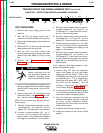
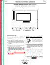
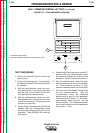
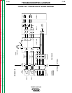
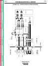
FIGURE F.47 - 6-PIN AMPHENOL LOCATION
1
2
TROUBLESHOOTING & REPAIR
TEST PROCEDURE
1. Remove the Remote Control Kit from the
power source.
2. Perform the following tests. If any test fails,
the Remote Control Kit is faulty and should
be replaced.
A. With the volt/ohmmeter, check the conti-
nuity between pin F of the 6-pin amphenol
and the case of the Remote Control Kit.
The reading should be zero ohms.
B. With the volt/ohmmeter, check the conti-
nuity between pin F and the other five pins
of the 6-pin amphenol. The reading should
be open (no continuity).
C. Set the Output Terminals switch to the ON
position. With the volt/ohmmeter, check
the continuity between pins D and E of the
amphenol. There SHOULD BE continuity
(zero ohms).
D. Set the Output Terminals switch to the OFF
position. With the volt/ohmmeter, check
the continuity between pins D and E of the
amphenol. There should be NO continuity.
E. With the volt/ohmmeter, check the resis-
tance between pins A and C of the amphe-
nol. There should be 10 Kohm (+/- 10%)
resistance between these pins at all times.
F. Turn the knob of the Remote Control Kit all
the way counterclockwise. With the
volt/ohmmeter, check the resistance
between pins A and B of the amphenol.
There should be 10 Kohm (+/- 10%) resis-
tance between these pins now. Turn the
knob clockwise. The resistance between
pins A and B should smoothly decrease to
zero ohms (+/- 10%).
POWER WAVE 450
Return to Section TOC Return to Section TOC Return to Section TOC Return to Section TOC
Return to Master TOC Return to Master TOC Return to Master TOC Return to Master TOC
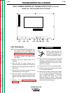
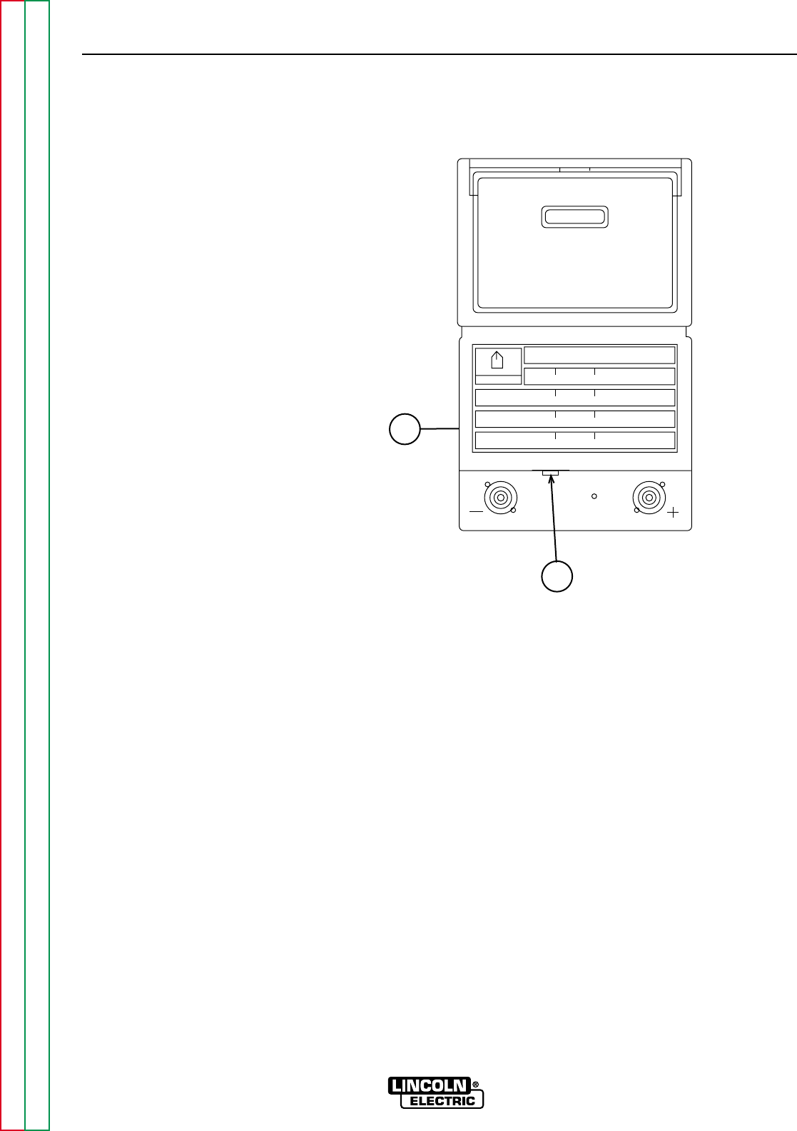
1. MACHINE FRONT PANEL
2. REMOTE CONTROL AMPHENOL RECEPTACLE (6-PIN)