


Return to Section TOC Return to Section TOC Return to Section TOC Return to Section TOC
Return to Master TOC Return to Master TOC Return to Master TOC Return to Master TOC
F-99 F-99
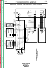
INTERNAL AND AUXILIARY SUPPLY VOLTAGE TEST (continued)
TROUBLESHOOTING & REPAIR
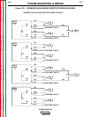
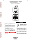
C. Protection Board:
115 VAC Between J34 - pin 8 and J34 -
pin 12 (Power Wave 450 only)
42 VAC Between J34 - pin 10 and J34
- pin 12
24 VAC Between J34 - pin 11 and J34
- pin 12
If any of these voltages are not present on the
protection board (and the voltages in part A,
above, were present, replace the protection
board.
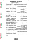
D. Power Board:
42 VAC Between J43 - pin 1 and J43 -
pin 3
If this voltage is not present (and the voltages
in part A, above, were present), disconnect
plug J35 from the protection board and check
for 42 VAC at header J35 between pin 1 and
pin 6. If this voltage is NOT present, replace
the protection board. If this voltage IS present,
check the wiring between the boards. Then
replace the power board.
E. Display Board:
+5 VDC Between J16 - pin 2 and J16 -
pin 3
+15 VDC Between J16 - pin 10 and J16
- pin 7
+5 VDC Between J16 - pin 1 and J16 -
pin 7
-5 VDC Between J16 - pin 9 and J16 -
pin 7
-8 VDC Between J16 - pin 6 and J16 -
pin 7
If any of these voltages are not present (and
the voltages in part D, above, were present),
disconnect plug J44 from the power board and
check the following voltages at header J44 on
the power board:
+5 VDC Between J44 - pin 3 and J44 -
pin 2
+15 VDC Between J44 - pin 10 and J44
- pin 12
+5 VDC Between J44 - pin 11 and J44
- pin 12
-5 VDC Between J44 - pin 9 and J44 -
pin 12
-8 VDC Between J44 - pin 6 and J44 -
pin 12
If any of these voltages are NOT present,
replace the power board. If these voltages ARE
present, check the wiring first. Then replace
the display board.
F. Control Board:
+15 VDC Between J22 - pin 10 and J22
- pin 12
-15 VDC Between J22 - pin 6 and J22-
pin 12
+5 VDC Between J22 - pin 11 and J22
- pin 12
If any of these voltages are not present (and
the voltages in part D, above, were present),
disconnect plug J42 from the power board and
check the following voltages at header J42 on
the power board:
+15 VDC Between J42 - pin 10 and J42
- pin 12
-15 VDC Between J42 - pin 6 and J42 -
pin 12
+5 VDC Between J42 - pin 11 and J42
- pin 12
If any of these voltages are NOT present,
replace the power board. If these voltages ARE
present, check the wiring. Then replace the
control board.
POWER WAVE 450