


Return to Section TOC Return to Section TOC Return to Section TOC Return to Section TOC
Return to Master TOC Return to Master TOC Return to Master TOC Return to Master TOC
F-95 F-95
DYNAMIC CAPACITOR BALANCE TEST (continued)
TROUBLESHOOTING & REPAIR
ELECTRIC SHOCK
can kill.
With input power ON, there
are high voltages inside the
machine, including the pro-
tection board. Do not reach into the machine
or touch any internal part of the machine while
power is ON.
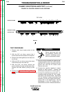
10. Turn input power ON. Machine output
must be OFF.
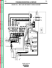
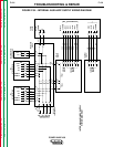
11. Measure the frequency between J23 - pin
4 and J23 - pin 2 on the control board.
You should see between 3.2 and 5.3 divi-
sions per cycle (950 to 1550 Hz.). If you
do see this, the test is completed. If you
do not see this, go to the next step.
12. Turn the power switch SW1 to the OFF
position, disconnect input power to the
machine, and perform the Capacitor
Discharge Procedure.
Before continuing with the test procedure, per-
form the capacitor discharge procedure to
avoid electric shock.
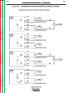
13. After you have completed the capacitor
discharge procedure for all four switch
boards, with the volt/ohmmeter, test leads
9J, 9K, 12J, and 12K for continuity
between the between the reconnect
switch and the protection board.
14. Test leads #232 and #234 for continuity.
These leads are between the protection
board and the control board. Lead #232 is
between J39 - pin 3 and J23 - pin 2. Lead
#234 is between J39 - pin 2 and J23 - pin
4. These leads must be intact for the fre-
quency signal to be measured, because
the transistor side of the optocoupler
needs the power from the control board.
15. If all the leads tested in step 14 are okay,
make sure that the molex plugs are all
plugged in correctly and pushed far
enough into their headers. Check the fre-
quency again on the oscilloscope.
16. If the frequency is still incorrect, the pro-
tection board may be faulty. Replace the
protection board and perform the
Dynamic Capacitor Balance Test again.
17. If the frequency is still incorrect, the con-
trol board may be faulty. Replace the con-
trol board.
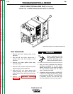
18. Install the machine case sides and top.
19. Install the handle and the lift bail rubber
gasket.
POWER WAVE 450
WARNING
WARNING