


TROUBLESHOOTING & REPAIR
F-207 F-207
POWER WAVE 450
Return to Section TOC Return to Section TOC Return to Section TOC Return to Section TOC
Return to Master TOC Return to Master TOC Return to Master TOC Return to Master TOC
PRE-POWERUP SWITCH BOARD TEST PROCEDURE
FOR REPLACEMENT OF SWITCH ASSEMBLY G2402-2 (continued)
8. Turn the variable AC primary supply to zero
volts and then turn it OFF. See Figure F.76.
9. Once the filter capacitor voltage drops to zero,
turn the arc start switch OFF. See Arc Start
PW450 or Figure F.79.
PREPARE MACHINE FOR NORMAL
OPERATION
1. Turn OFF the 115VAC pretest power circuit.
See Figure F.78
2. Make certain the filter capacitors are
completely discharged. Remove the variable
AC primary supply. See Figure F.76.
3. Remove the 115VAC pretest power circuit.
See Figure F.78.
4. Reconnect plug P70.
5. Remove the jumper plug in P23. See
Figure F.80
6. Reconnect P23.
7. Reconnect P73.
OUTPUT TESTS SETUP
The filter capacitors must be discharged
before continuing. Make sure the Power Wave
is configured for 460VAC operation.
1. Connect a power input cable to CR1. DO NOT
APPLY INPUT VOLTAGE AT THIS TIME.
2. Connect the grid load to the Power Wave out-
put terminals. Make sure the grid load is OFF.
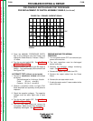
PRIMARY OVER CURRENT TEST
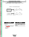
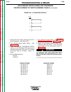
1. Connect a current probe to the oscilloscope
and set it for:
10 mV/div. (should be equal 10 mA/div.)
10 uS/div.
2. Put the current probe on lead 221 at J21
pin 1. See Wiring Diagram
3. Loosely assemble the sheet metal case to the
Power Wave.
4. Apply input power to the machine and turn the
Power Wave power switch ON.
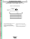
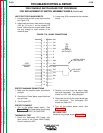
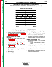
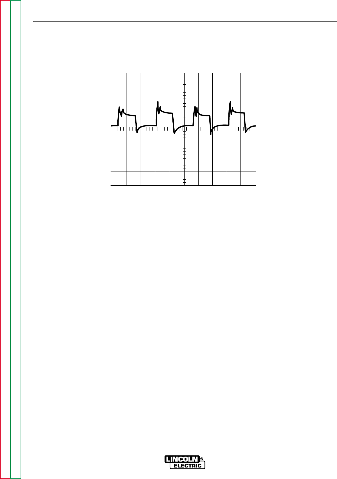
FIGURE F.83 - OUTPUT SIGNAL
0 V
5V/Div
10uS/Div