


Return to Section TOC Return to Section TOC Return to Section TOC Return to Section TOC
Return to Master TOC Return to Master TOC Return to Master TOC Return to Master TOC
F-83 F-83
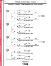
RECONNECT SWITCH TEST 1 (continued)
TROUBLESHOOTING & REPAIR
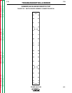
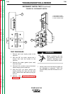
For 380 or 460 VAC:
A. Check that the following leads are connect-
ed together at the reconnect switch: #9A,
#9B, #9K, and POS.
B. Check that the following leads are con-
nected together at the reconnect switch:
#9C, #9D, #9J, #12A, #12B, and #12J.
C. Check that the following leads are con-
nected together at the reconnect switch:
#12C, #12D, #12K and NEG.
D. With the volt/ohmmeter, check that there is
no continuity between the three groups of
leads in A, B, and C above.
8. If any of the leads tested above are short-
ed, go to step 9. If none of the leads are
shorted, the test is complete. Install the
machine case sides, top, handle and the
lift bail rubber gasket.
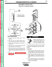
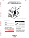
9. Perform the following steps:
A. With the 5/16" nut driver, remove the
screws that hold the PC board cover.
Remove the cover.
B. Disconnect plug J31 from the protection
board. If this eliminates the short, the pro-
tection board may be faulty. Replace the
protection board. If the short persists, go
to step 9C.
C. With the Phillips head screw driver, remove
the POS and NEG leads from the recon-
nect switch. If this eliminates the short,
either the input rectifier or the harness
(leads POS and NEG) between the input
rectifier and the reconnect switch is faulty.
Check the harness and if it is not faulty,
perform the Input Rectifier Test.
Reconnect leads POS and NEG to the
input rectifier. If the short persists, go to
step 9D.
D. Remove leads #9A, #9B, #9C, #9D, #12A,
#12B, #12C, and #12D from the four
switch boards. If this eliminates the short,
check these leads to make sure they are
not exposed, damaged, or shorted. If the
leads are okay, perform the Switch Board
Test and the Snubber and Bleeder
Resistor Test to find the cause of the
short. Reconnect leads #9A, #9B, #9C,
#9D, #12A, #12B, #12C, and #12D to the
four switch boards before conduction
these tests.
10. Replace the PC board cover and install the
machine case sides and top.
11. Install the handle and the lift bail rubber
gasket.
POWER WAVE 450