


Return to Section TOC Return to Section TOC Return to Section TOC Return to Section TOC
Return to Master TOC Return to Master TOC Return to Master TOC Return to Master TOC
F-105 F-105
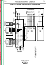
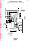
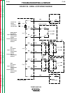
MAIN CONTACTOR TEST (continued)
TROUBLESHOOTING & REPAIR
A. With the power switch SW1 OFF, check to
see if leads L1A and L3A are shorted
together. If they are shorted, visually
inspect the leads. If the leads are okay,
then power switch SW1 is faulty and must
be replaced.
B. Remove leads L1, L2, and L3 from the
main contactor. Check if the terminals of
the main contactor are still shorted. If they
are, the main contactor is faulty and must
be replaced. If the terminals are not short-
ed, the input lines themselves are shorted.
Reconnect leads L1, L2, L3, L1A, and L3A
to the main contactor.
9. Visually inspect terminals T1, T2, and T3
of the main contactor. Make sure they are
not shorted together in any way. If they
are not shorted, go to step 11. If they are
shorted, go to step 10.
10. Remove leads T1, T2, and T3 from the
main contactor.
A. Check if the terminals of the main contac-
tor are still shorted. If they are, the main
contactor is faulty and must be replaced.
B. Reconnect leads T1, T2, and T3 to the
main contactor. Remove plug J30 from the
protection board. Make sure that leads T1
and T3 of plug J30 between the main con-
tactor and the protection board are not
damaged, exposed, or shorted together.
Check again for shorts across the contacts
of the main contactor. If the terminals are
not shorted now, the protection board is
faulty. Replace the protection board.
C. Visually inspect leads T1, T2, and T3
between the main contactor and the input
rectifier and between the main contactor
and the protection board. If these leads
are not damaged or exposed, then the
input rectifier may be faulty and should be
checked. Perform the Input Rectifier
Test described in this section of the man-
ual.
11. With the volt/ohmmeter, check for conti-
nuity between the following terminals of
the main contactor:
L1 and T1
L2 and T2
L3 and T3
If any of these measurements shows continu-
ity, replace the main contactor. If no continuity
is shown, go to step 12.
12. Visually check the following leads for
damage, then check for continuity as
described:
Lead #324 Between the main contactor
and plug J32 - pin 4 of the
protection board
Lead #326 Between the main contactor
and plug J32 - pin 6 of the
protection board
Lead #321 Between plug J71 - pin 1 of
auxiliary Transformer 1 and
plug J32 - pin 1 of the protec-
tion board
Lead #323 Between plug J71 - pin 4 of
auxiliary Transformer 1 and
plug J32 - pin 3 of the protec-
tion board
Lead T1 Between the main contactor
and the protection board plug
J30 - pin 11
Lead T3 Between the main contactor
and the protection board plug
J30 - pin 16
Put the power switch SW1 in the ON position
for the next two continuity tests:
Lead H1B Between terminal L3 of the
main contactor and plug J30
- pin 6 of the protection board
Lead #321A Between terminal L1 of the
main contactor and plug J30
- pin 1 of the protection board
Put the power switch SW1 in the OFF position.
Replace any broken or damaged leads discov-
ered by these tests.
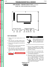
13. Connect any plugs disconnected for the
tests. Replace the PC board cover with
two sheet metal screws.
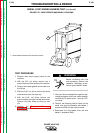
14. Install the machine case sides and top.
15. Install the handle and the lift bail rubber
gasket.
POWER WAVE 450