


F-190 F-190
OUTPUT RECTIFIER BRIDGE REMOVAL AND REPLACEMENT (continued)
TROUBLESHOOTING & REPAIR
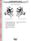
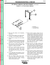
13. For reassembly, attach the glastic insulat-
ed angle mounting pieces to the heat sink
first. Slide the bridge into position and
then fasten the bottom tab to the sub-
frame with the bolt, split-ring lock washer
and nut. Then attach and tighten down
the top and bottom bolts that hold the
heat sink on both sides of the machine.
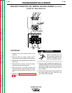
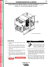
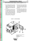
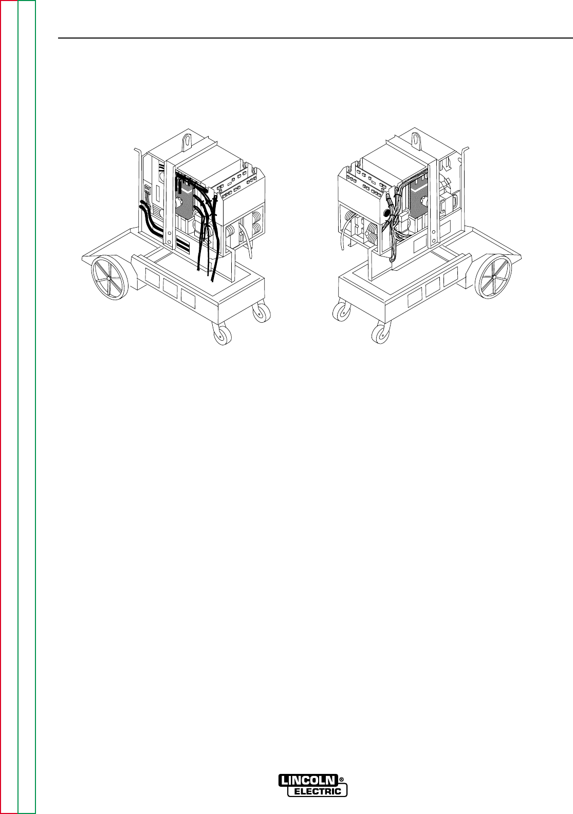
14. Reconnect the leads on both sides of the
bridge. Install new cable ties according to
Figure F.72.
15. Install the machine case sides and top.
16. Install the handle and the lift bail rubber
gasket.
POWER WAVE 450
Return to Section TOC Return to Section TOC Return to Section TOC Return to Section TOC
Return to Master TOC Return to Master TOC Return to Master TOC Return to Master TOC
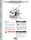
SECONDARY HARNESS ASSEMBLY (WHITE)
PRIMARY HARNESS ASSEMBLY (BLACK)
FIGURE F.72 – CABLE TIE LOCATIONS