


Return to Section TOC Return to Section TOC Return to Section TOC Return to Section TOC
Return to Master TOC Return to Master TOC Return to Master TOC Return to Master TOC
F-78 F-78
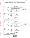
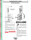
SNUBBER AND BLEEDER RESISTOR TEST (continued)
TROUBLESHOOTING & REPAIR
C. With the volt/ohmmeter, check for 25
ohms resistance between lead #404 and
#9F.
If the measurement reads between 20 and
30 ohms, resistor R4 and leads #404 and
#9F are okay. Go to step D.
If the measurement does not read between
20 and 30 ohms, check for continuity in
leads #404 and #9F. Then test for 25 ohms
resistance across R4 directly. If the mea-
surement does not read between 20 and
30 ohms, replace resistor R4.
D. Reconnect quick connect terminals #403,
#404, #9, and #12 on switch board 2.
Switch Board 3: (Switch Board 3 is Marked
CAP 1 on the Switch Board Assembly
Connection Decal - See Figure F.24.)
A. Remove quick connect terminals #405,
#406, #9, and #12 from switch board 3.
B. With the volt/ohmmeter, check for 25
ohms resistance between lead #405 and
#12G.
If the measurement reads between 20 and
30 ohms, resistor R5 and leads #405 and
#12G are okay. Go to step C.
If the measurement does not read between
20 and 30 ohms, check for continuity in
leads #405 and #12G. Then test for 25
ohms resistance across R5 directly. If the
measurement does not read between 20
and 30 ohms, replace resistor R5.
C. With the volt/ohmmeter, check for 25
ohms resistance between lead #406 and
#9G.
If the measurement reads between 20 and
30 ohms, resistor R6 and leads #406 and
#9G are okay. Go to step D.
If the measurement does not read between
20 and 30 ohms, check for continuity in
leads #406 and #9G. Then test for 25
ohms resistance across R5 directly. If the
measurement does not read between 20
and 30 ohms, replace resistor R5.
D. With the volt/ohmmeter, check for 7.5 K-
ohms resistance between lead #12G (12M)
and #9G (9M).
If the measurement reads between 6.75
and 8.25 K-ohms, resistor R10 and leads
#12G (12M) and #9G (9M) are okay. Go to
step E.
If the measurement does not read between
6.75 and 30 K-ohms, check for continuity
in leads #12G (12M) and #9G (9M). Then
test for 7.5 K-ohms resistance across R10
directly. If the measurement does not read
between 6.75 and 8.25 K-ohms, replace
resistor R10.
E. Reconnect quick connect terminals #405,
#406, #9, and #12 on switch board 3.
Switch Board 4: (Switch Board 4 is Marked
CAP 4 on the Switch Board Assembly
Connection Label - See Figure F.24.)
A. Remove quick connect terminals #407,
#408, #9, and #12 from switch board 4.
B. With the volt/ohmmeter, check for 25
ohms resistance between lead #407 and
#12H.
If the measurement reads between 20 and
30 ohms, resistor R7 and leads #407 and
#12H are okay. Go to step C.
If the measurement does not read between
20 and 30 ohms, check for continuity in
leads #407 and #12H. Then test for 25
ohms resistance across R3 directly. If the
measurement does not read between 20
and 30 ohms, replace resistor R7.
C. With the volt/ohmmeter, check for 25
ohms resistance between lead #408 and
#9H.
If the measurement reads between 20 and
30 ohms, resistor R8 and leads #408 and
#9H are okay. Go to step D.
If the measurement does not read between
20 and 30 ohms, check for continuity in
leads #408 and #9H. Then test for 25
ohms resistance across R8 directly. If the
measurement does not read between 20
and 30 ohms, replace resistor R8.
D. Reconnect quick connect terminals #407,
#408, #9, and #12 on switch board 4.
8. Install the machine case sides and top.
9. Install the handle and the lift bail rubber
gasket.
POWER WAVE 450