


110
CHAPTER 5 CPU ARCHITECTURE
70
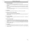
IE
PSW
Z RBS1 AC RBS0 0 ISP CY
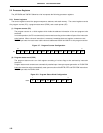
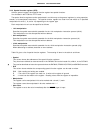
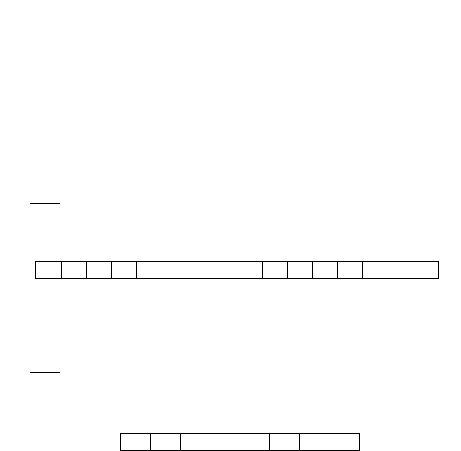
PC
15 0
PC15 PC14 PC13 PC12 PC11 PC10 PC9 PC8 PC7 PC6 PC5 PC4 PC3 PC2 PC1 PC0
5.2 Processor Registers
The
µ
PD78078 and 78078Y Subseries units incorporate the following processor registers.
5.2.1 Control registers
The control registers control the program sequence, statuses, and stack memory. The control registers consist
of a program counter (PC), a program status word (PSW), and a stack pointer (SP).
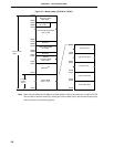
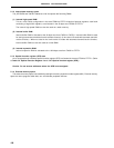
(1) Program counter (PC)
The program counter is a 16-bit register which holds the address information of the next program to be
executed.
In normal operation, the PC is automatically incremented according to the number of bytes of the instruction
to be fetched. When a branch instruction is executed, immediate data and register contents are set.
RESET input sets the reset vector table values at addresses 0000H and 0001H to the program counter.
Figure 5-7. Program Counter Configuration
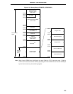
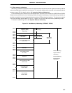
(2) Program status word (PSW)
The program status word is an 8-bit register consisting of various flags to be set/reset by instruction
execution.
Program status word contents are automatically stacked upon interrupt request generation or PUSH PSW
instruction execution and are automatically reset upon execution of the RETB, RETI and POP PSW
instructions.
RESET input sets the PSW to 02H.
Figure 5-8. Program Status Word Configuration