


242
CHAPTER 9 8-BIT TIMER/EVENT COUNTERS 1 AND 2
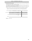
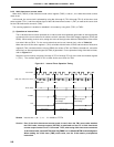
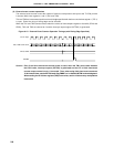
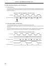
Count Clock
TMS (TM1, TM2) Count Value
CR10, CR20
INTTM2
TO2
Interval Time Interval Time Interval Time
Interrupt Request
Acknowledge
Interrupt Request
Acknowledge
NN NN
Count Start Clear Clear
0000 0001 N 0000 0001 N 0000 0001 N
t
9.4.2 16-bit timer/event counter mode
When bit 2 (TMC12) of the 8-bit timer mode control register (TMC1) is set to 1, the 16-bit timer/event counter
mode is set.
In this mode, the count clock is selected by using bits 0 through 3 (TCL10 through TCL13) of the timer clock
select register (TCL1), and the overflow signal of the 8-bit timer/event counter 1 (TM1) is used as the count clock
for the 8-bit timer/event counter 2 (TM2).
The counting operation is enabled or disabled in this mode by using bit 0 (TCE1) of TMC1.
(1) Operation as interval timer
The 16-bit timer/event counter operates as an interval timer that repeatedly generates an interrupt request
at intervals of the count values set in advance to the 2 channels of the 8-bit compare registers (CR10 and
CR20). When setting a count value, assign the value of the high-order 8 bits to CR20 and the value of the
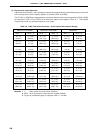
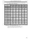
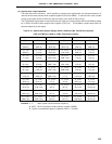
low-order 8 bits to CR10. For the count values that can be set (interval time), refer to Table 9-9.
When the value of 8-bit timer register 1 (TM1) coincides with the value of CR10 and the value of 8-bit timer
register 2 (TM1) coincides with the value of CR20, the values of TM1 and TM2 are cleared to 0, and at the
same time, an interrupt request signal (INTTM2) is generated. For the operation timing of the interval timer,
refer to Figure 9-11.
Select the count clock by using bits 0 through 3 (TCL10 through TCL13) of the timer clock select register
1 (TCL1). The overflow signal of TM1 is used as the count clock for TM2.
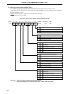
Figure 9-11. Interval Timer Operation Timing
Remark Interval time = (N + 1) x t : N = 0000H to FFFFH
Caution Even if the 16-bit timer/event counter mode is used, when the TM1 count value matches
the CR10 value, interrupt request (INTTM1) is generated and the F/F of 8-bit timer/event
counter output control circuit 1 is inverted. Thus, when using 8-bit timer/event counter as
16-bit interval timer, set the INTTM1 mask flag TMMK1 to 1 to disable INTTM1 acknowledgment.
When reading the 16-bit timer (TMS) count value, use the 16-bit memory manipulation
instruction.