


193
CHAPTER 8 16-BIT TIMER/EVENT COUNTER
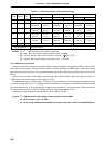
Cautions 1. Switch the clear mode and the T00 output timing after stopping the timer operation (by
setting TMC01 to TMC03 to 0, 0, 0).
2. Set the valid edge of the TI00/INTP0 pin with an external interrupt mode register 0
(INTM0) and select the sampling clock frequency with a sampling clock select register
(SCS).
3. When using the PWM mode, set the PWM and then set data to CR00.
4. If the mode is set so that the timer is cleared and starts when TM0 and CR00 match,
the OVF0 flag is set to 1 when the TM0 value changes from 0FFFFH to 0000H with CR00
set to FFFFH.
Remark TO0 : 16-bit timer/event counter output pin
TI00 : 16-bit timer/event counter input pin
TM0 : 16-bit timer register
CR00 : Compare register 00
CR01 : Compare register 01
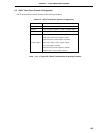
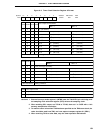
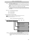
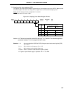
(3) Capture/compare control register 0 (CRC0)
This register controls the operation of the capture/compare registers (CR00, CR01).
CRC0 is set with a 1-bit or 8-bit memory manipulation instruction.
RESET input sets CRC0 value to 04H.
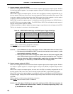
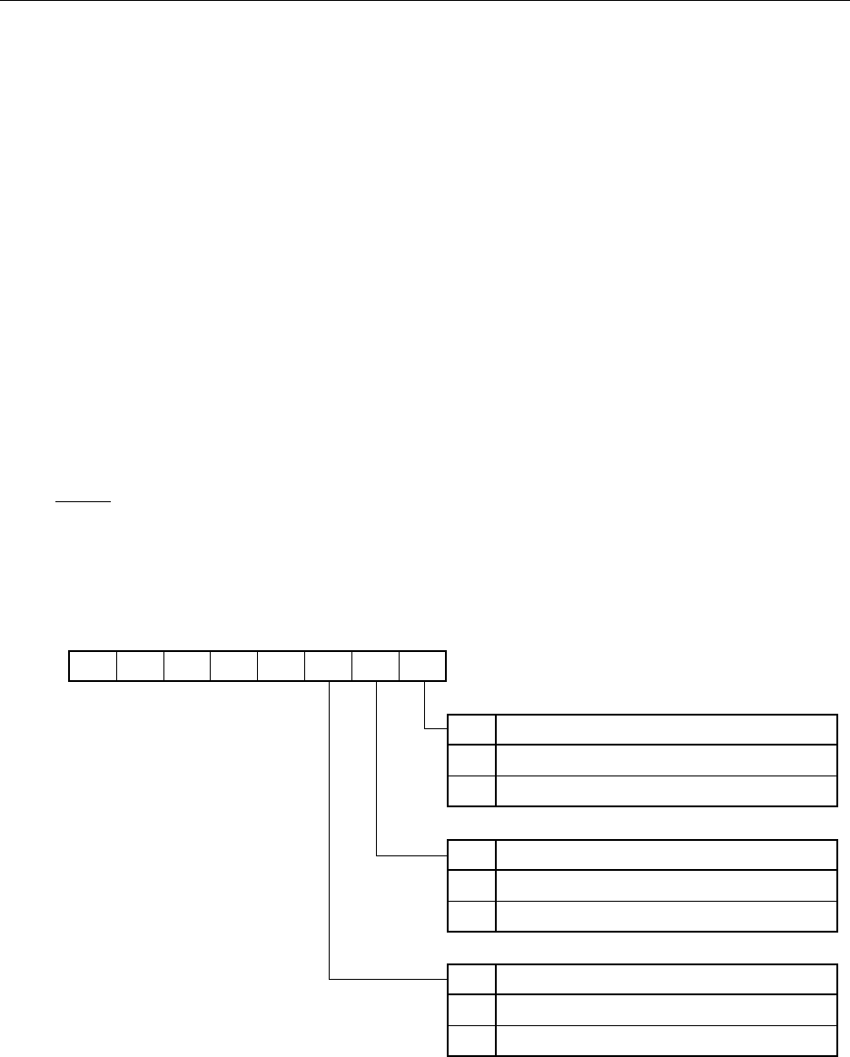
Figure 8-5. Capture/Compare Control Register 0 Format
Cautions 1. Timer operation must be stopped before setting CRC0.
2. When clear & start mode on a match between TM0 and CR00 is selected with the
16-bit timer mode control register, CR00 should not be specified as a capture
register.
0000
0 CRC02 CRC01 CRC00
76543210Symbol
CRC0
FF4CH 04H R/W
Address After Reset R/W
CRC00
CR00 Operating Mode Selection
0
Operates as compare register
1
Operates as capture register
CRC01
CR00 Capture Trigger Selection
Captures on valid edge of TI01
Captures on valid edge of TI00
0
1
CRC02
CR01 Operating Mode Selection
Operates as compare register
Operates as capture register
0
1