


259
CHAPTER 10 8-BIT TIMER/EVENT COUNTERS 5 AND 6
10.4 8-Bit Timer/Event Counters 5 and 6 Operations
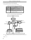
10.4.1 Interval timer operations
Setting the 8-bit timer mode control registers (TMC5 and TMC6) as shown in Figure 10-8 allows operation as
an interval timer. Interrupt requests are generated repeatedly using the count value preset in 8-bit compare registers
(CR50 and CR60) as the interval.
When the count value of the 8-bit timer register 5 or 6 (TM5, TM6) matches the value set to CR50 or CR60,
counting continues with the TM5 or TM6 value cleared to 0 and the interrupt request signal (INTTM5, INTTM6) is
generated.
Count clock of the 8-bit timer register 5 (TM5) can be selected with the timer clock select register 5 (TCL5) and
count clock of the 8 bit timer register 6 (TM6) can be selected with the timer clock select register 6 (TCL6).
For the operation in the case the value of the compare register is changed during the timer count operation, refer
to 10.5 8-Bit Timer/Event Counters 5 and 6 Precautions (3).
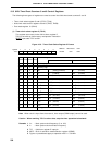
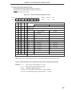
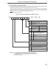
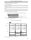
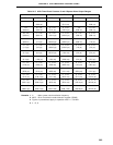
Figure 10-8. 8-Bit Timer Mode Control Register Settings for Interval Timer Operation
Remarks 1. 0/1 : Setting 0 or 1 allows another function to be used simultaneously with the interval timer.
See 10.3 (3), (4) for details.
2. n = 5, 6
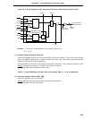
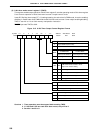
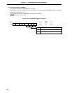
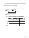
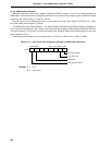
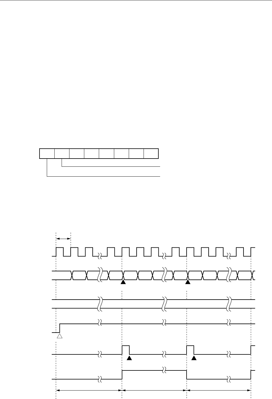
Figure 10-9. Interval Timer Operation Timings
Remarks 1. Interval time = (N + 1) x t : N = 00H to FFH
2. n = 5, 6
1
TCEn
0
TMCn6
0 0 0/1
LVSn LVRn TMCn1 TOEn
TMCn
0/1 0/1 0/1
Clear and start on match of TMn and CRn0
TMn operation enable
t
00 01 N 00 01 N 00 01 N
NNNN
Clear Clear
Count Start
Interrupt Request Acknowledge
Interrupt Request
Acknowledge
Interval Time Interval Time Interval Time
Count Clock
TMn Count Value
CRn0
TCEn
INTTMn
TOn