


281
CHAPTER 12 WATCHDOG TIMER
12.4 Watchdog Timer Operations
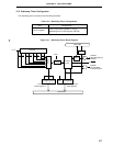
12.4.1 Watchdog timer operation
When bit 4 (WDTM4) of the watchdog timer mode register (WDTM) is set to 1, the watchdog timer is operated
to detect any runaway.
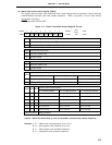
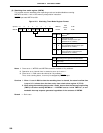
The watchdog timer count clock (runaway detection time interval) can be selected with bits 0 to 2 (TCL20 to
TCL22) of the timer clock select register 2 (TCL2).
Watchdog timer starts by setting bit 7 (RUN) of WDTM to 1. After the watchdog timer is started, set RUN to 1
within the set runaway detection time interval. The watchdog timer can be cleared and counting is started by setting
RUN to 1. If RUN is not set to 1 and the runaway detection time is past, system reset or a non-maskable interrupt
request is generated according to the WDTM bit 3 (WDTM3) value.
The watchdog timer can be cleared when RUN is set to 1.
The watchdog timer continues operating in the HALT mode but it stops in the STOP mode. Thus, set RUN to
1 before the STOP mode is set, clear the watchdog timer and then execute the STOP instruction.
Cautions 1. The actual runaway detection time may be shorter than the set time by a maximum of
0.5 %.
2. When the subsystem clock is selected for CPU clock, watchdog timer count operation is
stopped.
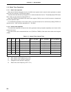
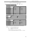
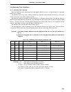
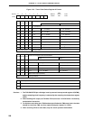
Table 12-4. Watchdog Timer Runaway Detection Time
TCL22 TCL21 TCL20 Runaway Detection Time MCS = 1 MCS = 0
000 2
11
x 1/fXX 2
11
x 1/fX (410
µ
s) 2
12
x 1/fX (819
µ
s)
001 2
12
x 1/fXX 2
12
x 1/fX (819
µ
s) 2
13
x 1/fX (1.64 ms)
010 2
13
x 1/fXX 2
13
x 1/fX (1.64 ms) 2
14
x 1/fX (3.28 ms)
011 2
14
x 1/fXX 2
14
x 1/fX (3.28 ms) 2
15
x 1/fX (6.55 ms)
100 2
15
x 1/fXX 2
15
x 1/fX (6.55 ms) 2
16
x 1/fX (13.1 ms)
101 2
16
x 1/fXX 2
16
x 1/fX (13.1 ms) 2
17
x 1/fX (26.2 ms)
110 2
17
x 1/fXX 2
17
x 1/fX (26.2 ms) 2
18
x 1/fX (52.4 ms)
111 2
19
x 1/fXX 2
19
x 1/fX (104.9 ms) 2
20
x 1/fX (209.7 ms)
Remarks 1. f
XX : Main system clock frequency (fX or fX/2)
2. f
X : Main system clock oscillation frequency
3. MCS : Bit 0 of oscillation mode selection register (OSMS)
4. TCL20 to TCL22 : Bits 0 to 2 of timer clock select register 2 (TCL2)
5. Figures in parentheses apply to operation with f
X = 5.0 MHz.