


111
CHAPTER 5 CPU ARCHITECTURE
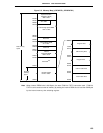
(a) Interrupt enable flag (IE)
This flag controls the interrupt request acknowledge operations of the CPU.
When IE = 0, the IE is set to interrupt disabled (DI) status. All interrupts except non-maskable interrupt
are disabled.
When IE = 1, the IE is set to interrupt enabled (EI) status and interrupt request acknowledge is controlled
with an in-service priority flag (ISP), an interrupt mask flag for various interrupt sources, and a priority
specification flag.
The IE is reset to (0) upon DI instruction execution or interrupt request acknowledgement and is set
to (1) upon EI instruction execution.
(b) Zero flag (Z)
When the operation result is zero, this flag is set (1). It is reset (0) in all other cases.
(c) Register bank select flags (RBS0 and RBS1)
These are 2-bit flags to select one of the four register banks.
In these flags, the 2-bit information which indicates the register bank selected by SEL RBn instruction
execution is stored.
(d) Auxiliary carry flag (AC)
If the operation result has a carry from bit 3 or a borrow at bit 3, this flag is set (1). It is reset (0) in
all other cases.
(e) In-service priority flag (ISP)
This flag manages the priority of acknowledgeable maskable vectored interrupts. When ISP = 0,
acknowledgment of the vectored interrupt request specified to low-order priority with the priority specify
flag registers (PR0L, PR0H, and PR1L) (refer to 22.3 (3) Priority specify flag registers (PR0L, PR0H,
and PR1L)) is disabled. Whether an actual interrupt request is acknowledged or not is controlled with
the interrupt enable flag (IE).
(f) Carry flag (CY)
This flag stores overflow and underflow upon add/subtract instruction execution. It stores the shift-out
value upon rotate instruction execution and functions as a bit accumulator during bit manipulation
instruction execution.