


289
CHAPTER 14 BUZZER OUTPUT CONTROL CIRCUIT
14.1 Buzzer Output Control Circuit Functions
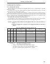
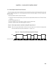
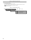
The buzzer output control circuit outputs 1.2-kHz, 2.4-kHz, 4.9-kHz, or 9.8-kHz frequency square waves. The
buzzer frequency selected with timer clock select register 2 (TCL2) is output from the BUZ/P36 pin.
Follow the procedure below to output the buzzer frequency.
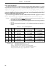
(1) Select the buzzer output frequency with bits 5 to 7 (TCL25 to TCL27) of TCL2.
(2) Set the P36 output latch to 0.
(3) Set bit 6 (PM36) of port mode register 3 (PM3) to 0 (Set to output mode).
Caution Buzzer output cannot be used when setting P36 output latch to 1.
14.2 Buzzer Output Control Circuit Configuration
The buzzer output control circuit consists of the following hardware.
Table 14-1. Buzzer Output Control Circuit Configuration
Item Configuration
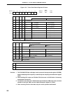
Timer clock select register 2 (TCL2)
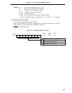
Port mode register 3 (PM3)
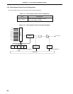
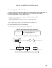
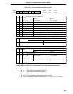
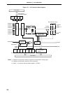
Figure 14-1. Buzzer Output Control Circuit Block Diagram
Control register
Internal Bus
f
XX
/2
9
f
XX
/2
10
f
XX
/2
11
TCL27 TCL26 TCL25
3
PM36
Selector
Timer Clock Select Register 2
Port Mode Register 3
BUZ/P36
P36
Output Latch