


398
CHAPTER 18 SERIAL INTERFACE CHANNEL 0 (
µ
PD78078Y Subseries)
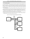
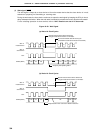
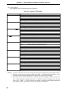
(4) Various signals
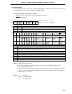
A list of signals in the I
2
C bus mode is given in Table 18-4.
Table 18-4. Signals in I
2
C Bus Mode
Signal name Description
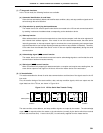
Start condition Definition : SDA0 (SDA1) falling edge when SCL is high (Note 1)
Function :
Indicates that serial communication starts and subsequent data are address data.
Signaled by : Master
Signaled when : CMDT is set.
Affected flag(s) : CMDD (is set.)
Stop condition Definition : SDA0 (SDA1) rising edge when SCL is high (Note 1)
Function : Indicates end of serial transmission.
Signaled by : Master
Signaled when : RELT is set.
Affected flag(s) : RELD (is set) and CMDD (is cleared)
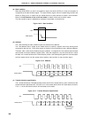
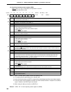
Acknowledge signal (ACK) Definition : Low level of SDA0 (SDA1) pin during one SCL clock cycle after serial reception
Function : Indicates completion of reception of 1 byte.
Signaled by : Master or slave
Signaled when : ACKT is set with ACKE = 1.
Affected flag(s) : ACKD (is set.)
Wait (WAIT) Definition : Low-level signal output to SCL
Function : Indicates state in which serial reception is not possible.
Signaled by : Slave
Signaled when : WAT1, WAT0 = 1x.
Affected flag(s) : None
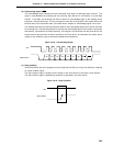
Serial Clock (SCL) Definition : Synchronization clock for output of various signals
Function : Serial communication synchronization signal.
Signaled by : Master
Signaled when : See Note 2 below.
Affected flag(s) : CSIIF0. Also see Note 3 below.
Address (A6 to A0) Definition : 7-bit data synchronized with SCL immediately after start condition signal
Function : Indicates address value for specification of slave on serial bus.
Signaled by : Master
Signaled when : See Note 2 below.
Affected flag(s) : CSIIF0. Also see Note 3 below.
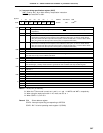
Transfer direction (R/W) Definition : 1-bit data output in synchronization with SCL after address output
Function : Indicates whether data transmission or reception is to be performed.
Signaled by : Master
Signaled when : See Note 2 below.
Affected flag(s) : CSIIF0. Also see Note 3 below.
Data (D7 to D0)) Definition : 8-bit data synchronized with SCL, not immediately after start condition
Function : Contains data actually to be sent.
Signaled by : Master or slave
Signaled when : See Note 2 below.
Affected flag(s) : CSIIF0. Also see Note 3 below.
Notes 1. The level of the serial clock can be controlled by CLC of the interrupt timing specify register (SINT).
2. Execution of instruction to write data to SIO0 when CSIE0 = 1 (serial transfer start directive). In the
wait state, the serial transfer operation will be started after the wait state is released.
3. If the 8-clock wait is selected when WUP = 0, CSIIF0 is set at the rising edge of the 8th clock cycle of
SCL. If the 9-clock wait is selected when WUP = 0, CSIIF0 is set at the rising edge of the 9th clock
cycle of SCL. If WUP = 1, CSIIF0 is set when an address is received and the address matches the
slave address register (SVA) value and when a stop condition is detected.