


293
CHAPTER 15 A/D CONVERTER
15.1 A/D Converter Functions
The A/D converter converts an analog input into a digital value. It consists of 8 channels (ANI0 to ANI7) with
an 8-bit resolution.
The conversion method is based on successive approximation and the conversion result is held in the 8-bit A/
D conversion result register (ADCR).
The following two ways are available to start A/D conversion.
(1) Hardware start
Conversion is started by trigger input (INTP3).
(2) Software start
Conversion is started by setting the A/D converter mode register (ADM).
One channel of analog input is selected from ANI0 to ANI7 and A/D conversion is carried out. In the case of
hardware start, A/D conversion operation stops and an interrupt request (INTAD) is generated when an A/D
conversion operation ends. In the case of software start, the A/D conversion operation is repeated. Each time an
A/D conversion operation ends, an interrupt request (INTAD) is generated.
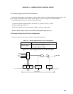
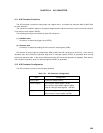
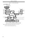
15.2 A/D Converter Configuration
The A/D converter consists of the following hardware.
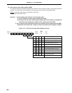
Table 15-1. A/D Converter Configuration
Item Configuration
Analog input 8 channels (ANI0 to ANI7)
Control register A/D converter mode register (ADM)
A/D converter input select register (ADIS)
External interrupt mode register 1 (INTM1)
Register Successive approximation register (SAR)
A/D conversion result register (ADCR)