


523
CHAPTER 22 INTERRUPT FUNCTIONS
22.5 Test Functions
In this function, when the watch timer overflows and when a rising edge of port 4 is detected, the corresponding
test input flag is set (1), and a standby release signal is generated.
Unlike the interrupt function, vectored processing is not performed.
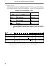
There are two test input factors as shown in Table 22-5. The basic configuration is shown in Figure 22-18.
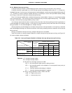
Table 22-5. Test Input Factors
Test Input Factors
Name Trigger
INTWT Clock timer overflow Internal
INTPT4 Negative edge detection at port 4 External
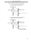
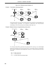
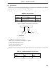
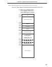
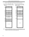
Figure 22-18. Basic Configuration of Test Function
IF : Test input flag
MK: Test mask flag
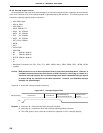
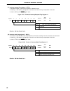
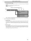
22.5.1 Registers controlling the test function
The test function is controlled by the following three registers.
• Interrupt request flag register 1L (IF1L)
• Interrupt mask flag register 1L (MK1L)
• Key return mode register (KRM)
The names of the test input flag and test mask flag corresponding to the test input signals are listed in Table
22-6.
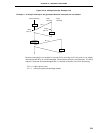
Table 22-6. Flags Corresponding to Test Input Signals
Test Input Signal Name Test Input Flag Test Mask Flag
INTWT WTIF WTMK
INTPT4 KRIF KRMK
Internal/
external
Internal bus
MK
IF
Test input
signal
Standby
release signal