


392
CHAPTER 18 SERIAL INTERFACE CHANNEL 0 (
µ
PD78078Y Subseries)
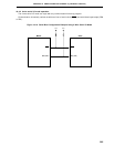
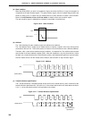
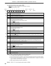
(a) Start condition
When the SDA0 (SDA1) pin level is changed from high to low while the SCL pin is high, this transition is
recognized as the start condition signal. This start condition signal, which is created using the SCL and
SDA0 (or SDA1) pins, is output from the master device to slave devices to initiate a serial transfer.
Refer to 18.4.5 Cautions on use of I
2
C bus mode, for details of the start condition output.
The start condition signal is detected by hardware incorporated in slave devices.
Figure 18-15. Start Condition
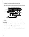
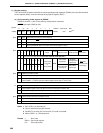
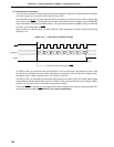
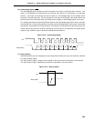
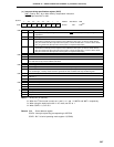
(b) Address
The 7 bits following the start condition signal are defined as an address.
The 7-bit address data is output by the master device to specify a specific slave from among those
connected to the bus line. Each slave device on the bus line must therefore have a different address.
Therefore, after a slave device detects the start condition, it compares the 7-bit address data received
and the data of the slave address register (SVA). After the comparison, only the slave device in which
the data are a match becomes the communication partner, and subsequently performs communication
with the master device until the master device sends a start condition or stop condition signal.
Figure 18-16. Address
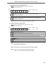
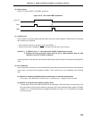
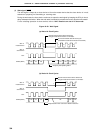
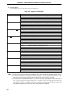
(c) Transfer direction specification
The 1 bit that follows the 7-bit address data will be sent from the master device, and it is defined as the
transfer direction specification bit. If this bit is 0, it is the master device which will send data to the slave.
If it is 1, it is the slave device which will send data to the master.
Figure 18-17. Transfer Direction Specification
H
SCL
SDA0 (SDA1)
1234567
A6 A5 A4 A3 A2 A1 A0 R/W
Address
SCL
SDA0 (SDA1)
234567
A6 A5 A4 A3 A2 A1 A0 R/W
Transfer direction
specification
SCL
81
SDA0 (SDA1)