


527
CHAPTER 23 EXTERNAL DEVICE EXPANSION FUNCTION
23.1 External Device Expansion Functions
The external device expansion functions connect external devices to areas other than the internal ROM, RAM,
and SFR.
The external device expansion function can be used in the following two modes:
• Multiplexed bus mode
• Separate bus mode
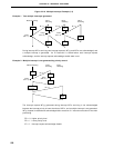
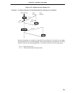
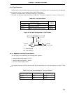
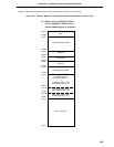
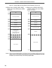
(1) Multiplexed bus mode
External devices are connected via the multiplexed address/data bus. Connecting external devices using
this mode may reduce the number of ports to be used. In this mode, ports 4 through 6 are used for control
of address/data, reafd/write strobe, wait, address strobe as shown below.
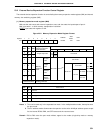
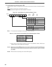
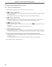
Table 23-1. Pin Functions in External Memory Expansion Mode
Pin function at external device connection Alternate function
Name Function
AD0 to AD7 Multiplexed address/data bus P40 to P47
A8 to A15 Upper Address bus P50 to P57
RD Read strobe signal P64
WR Write strobe signal P65
WAIT Wait signal P66
ASTB Address strobe signal P67
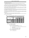
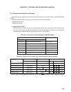
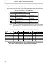
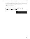
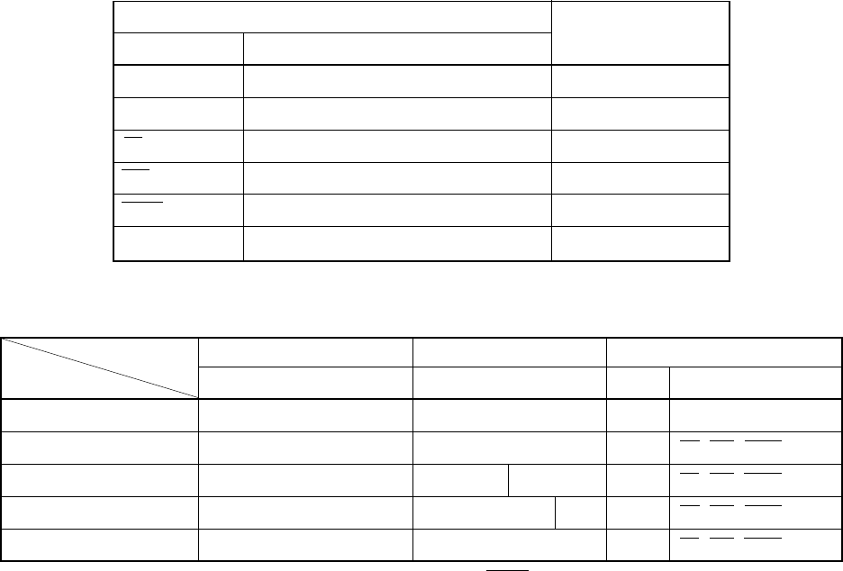
Table 23-2. State of Port 4 to Port 6 Pins in External Memory Expansion Mode
Ports and bits Port 4 Port 5 Port 6
Modes 0 to 7 0 1 2 3 4 5 6 7 0 to 3 4 to 7
Single-chip mode Port Port Port Port
256-byte expansion mode Address/data Port Port RD, WR, WAIT, ASTB
4-Kbyte expansion mode Address/data Address Port Port RD, WR, WAIT, ASTB
16-Kbyte expansion mode Address/data Address Port Port RD, WR, WAIT, ASTB
Full address mode Address/data Address Port RD, WR, WAIT, ASTB
Caution When the external wait function is not used, the WAIT pin can be used as a port in all modes.