


376
CHAPTER 18 SERIAL INTERFACE CHANNEL 0 (
µ
PD78078Y Subseries)
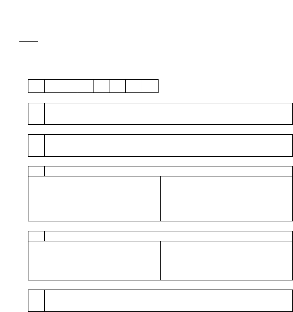
<6> <5> <4> <3> <2> <1> <0><7>
Symbol
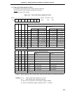
SBIC BSYE ACKD ACKE ACKT CMDD RELD CMDT RELT
RELT
Used for stop condition signal output.
When RELT = 1, SO0 Iatch is set to 1. After SO0 latch setting, automatically cleared to 0.
Also cleared to 0 when CSIE0 = 0.
R/W
FF61H 00H R/W
Note
Address After Reset R/W
CMDT
Used for start condition signal output.
When CMDT = 1, SO0 Iatch is cleared to 0. After SO0 latch clearance, automatically cleared to 0.
Also cleared to 0 when CSIE0 = 0.
R/W
R
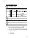
RELD Stop Condition Detection
Set Conditions (RELD = 1)Clear Conditions (RELD = 0)
• When stop condition signal is detected
• When transfer start instruction is executed
• If SIO0 and SVA values do not match in
address reception
• When CSIE0 = 0
• When RESET input is applied
R
CMDD Start Condition Detection
Clear Conditions (CMDD = 0)
• When transfer start instruction is executed
• When stop condition signal is detected
• When CSIE0 = 0
• When RESET input is applied
Set Conditions (CMDD = 1)
• When start condition signal is detected
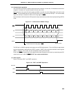
ACKT
Used to generate the ACK signal by software when 8-clock wait mode is selected.
Keeps SDA0 (SDA1) low from set instruction (ACKT = 1) execution to the next falling edge of SCL.
Also cleared to 0 upon start of serial interface transfer or when CSIE0 = 0.
R/W
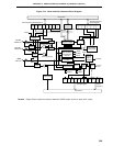
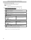
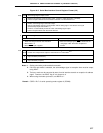
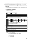
(3) Serial bus interface control register (SBIC)
This register sets serial bus interface operation and displays statuses.
SBIC is set with a 1-bit or 8-bit memory manipulation instruction.
RESET input sets SBIC to 00H.
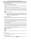
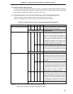
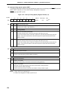
Figure 18-5. Serial Bus Interface Control Register Format (1/2)
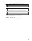
Note Bits 2, 3, and 6 (RELD, CMDD and ACKD) are read-only bits.
Remark CSIE0 : Bit 7 of serial operating mode register 0 (CSIM0)