


351
CHAPTER 17 SERIAL INTERFACE CHANNEL 0 (
µ
PD78078 SUBSERIES)
(6) Address match detection method
In the SBI mode, a particular slave device can be selected by transmitting slave address from the master
device.
Address match detection can be automatically executed by hardware. With slave address register, CSIIF0
is set only when the wake-up function specify bit (WUP) = 1 and the address transmitted from the master
device matches the value set to SVA.
When bit 5 (SIC) of the interrupt timing specify register (SINT) is set (1), the wake-up function does not
operate even if WUP is set (1) (the interrupt request signal is generated when a bus release is detected).
When using the wake-up function, clear SIC to 0.
Cautions 1. Slave selection/non-selection is detected by matching of the slave address received
after bus release (RELD = 1).
For this match detection, match interrupt request (INTCSI0) of the address to be
generated with WUP = 1 is normally used. Thus, execute selection/non-selection
detection by slave address when WUP = 1.
2. When detecting selection/non-selection without the use of interrupt request with WUP
= 0, do so by means of transmission/reception of the command preset by program
instead of using the address match detection method.
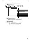
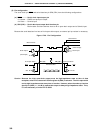
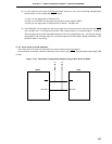
(7) Error detection
In the SBI mode, the serial bus SB0 (SB1) status being transmitted is fetched into the destination device,
that is, the serial I/O shift register 0 (SIO0). Thus, transmit errors can be detected in the following way.
(a) Method of comparing SIO0 data before transmission to that after transmission
In this case, if two data differ from each other, a transmit error is judged to have occurred.
(b) Method of using the slave address register (SVA)
Transmit data is set to both SIO0 and SVA and is transmitted. After termination of transmission, COI
bit (match signal coming from the address comparator) of the serial operating mode register 0 (CSIM0)
is tested. If “1”, normal transmission is judged to have been carried out. If “0”, a transmit error is judged
to have occurred.
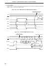
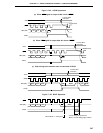
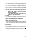
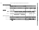
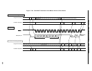
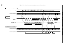
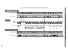
(8) Communication operation
In the SBI mode, the master device selects normally one slave device as communication target from among
two or more devices by outputting an “address” to the serial bus.
After the communication target device has been determined, commands and data are transmitted/received
and serial communication is realized between the master and slave devices.
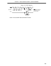
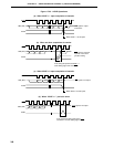
Figures 17-27 to 17-30 show data communication timing charts.
Shift operation of the serial I/O shift register 0 (SIO0) is carried out at the falling edge of serial clock (SCK0).
Transmit data is latched into the SO0 latch and is output with MSB set as the first bit from the SB0/P25 or
SB1/P26 pin. Receive data input to the SB0 (or SB1) pin at the rising edge of SCK0 is latched into the SIO0.