


420
CHAPTER 19 SERIAL INTERFACE CHANNEL 1
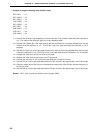
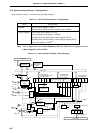
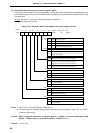
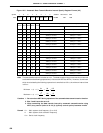
(3) Automatic data transmit/receive control register (ADTC)
This register sets automatic receive enable/disable, the operating mode, strobe output enable/disable, busy
input enable/disable, and error check enable/disable, and displays automatic transmit/receive execution and
error detection.
ADTC is set with a 1-bit or 8-bit memory manipulation instruction.
RESET input sets ADTC to 00H.
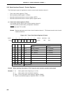
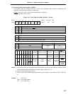
Figure 19-4. Automatic Data Transmit/Receive Control Register Format
Notes 1. Bits 3 and 4 (TRF and ERR) are read-only bits.
2. The termination of automatic transmission/reception should be judged by using TRF, not CSIIF1
(interrupt request flag).
Caution When an external clock input is selected with bit 1 (CSIM11) of the serial operating mode
register 1 (CSIM1) set to 0, set STRB and BUSY1 of ADTC to 0, 0.
Remark x: Don’t care
<6> <5> <4> <3> <2> <1> <0><7>
Symbol
ADTC RE ARLD ERCE ERR TRF STRB
BUSY1 BUSY0
FF69H 00H R/W
Note 1
Address After Reset R/W
BUSY1
0
1
1
Busy Input Control
Not using busy input
Busy input enable (active high)
Busy input enable (active low)
BUSY0
x
0
1
STRB
0
1
Strobe Output Control
Strobe output disable
Strobe output enable
TRF
1
Status in Automatic Transmit/Receive Function
Note 2
Detection of termination of automatic transmission/
reception (This bit is set to 0 upon suspension of
automatic transmission/reception or when ARLD = 0.)
During automatic transmission/reception
(This bit is set to 1 when data is written to SIO1.)
R/W
R/W
R
R
ERR
0
1
Error Detection in Automatic Transmit/Receive Function
No error
(Set to 0 when data is written to SIO1)
Error occurred
R/W
ARLD
0
1
Operating Mode for Automatic Transmit/Receive Function
Single operating mode
Repetitive operating mode
R/W
RE
0
1
Receive operation in Automatic Transmit/Receive Function
Receive disable
Receive enable
R/W
ERCE
0
Error Check in Automatic Transmit/Receive
Function
Error check disable
Error check enable (only when BUSY1 = 1)
0
1