


252
CHAPTER 10 8-BIT TIMER/EVENT COUNTERS 5 AND 6
10.2 8-Bit Timer/Event Counters 5 and 6 Configurations
The 8-bit timer/event counters 5 and 6 consist of the following hardware.
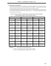
Table 10-3. 8-Bit Timer/Event Counters 5 and 6 Configurations
Item Configuration
Timer register 8 bits x 2 (TM5, TM6)
Register Compare register: 8 bits x 2 (CR50, CR60)
Timer output 2 (TO5, TO6)
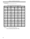
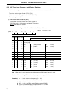
Timer clock select register 5 and 6 (TCL5, TCL6)
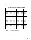
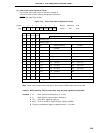
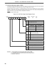
Control register 8-bit timer mode control registers 5 and 6 (TMC5, TMC6)
Port mode register 10 (PM10)
Note
Note Refer to Figure 6-20 Block Diagram of P100 and P101.
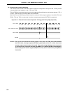
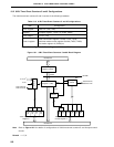
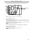
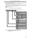
Figure 10-1. 8-Bit Timer/Event Counters 5 and 6 Block Diagram
Note Refer to Figure 10-2 for details of configurations of 8-bit timer/event counters 5 and 6 output control
circuits.
Remark n = 5, 6
TI5/P100/TO5
TI6/P101/TO6
Internal Bus
8-Bit Compare
Register (CRn0)
Match
8-Bit Timer
Register n (TMn)
4
Selector
2
Clear
6
OVF
Internal Bus
TCL
n3
TCL
n2
TCL
n1
TCL
n0
Timer Clock Select
Register n
Output
Control
Note
8-Bit Timer Mode
Control Register n
INTTMn
TO5/P100/TI5,
TO6/P101/TI6
TMC
n6
LVS
n
LVR
n
TMC
n1
TOE
n
TCE
n
f
XX
-f
XX
/2
10
f
XX
/2
12
Selector