


450
CHAPTER 19 SERIAL INTERFACE CHANNEL 1
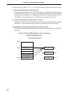
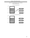
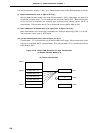
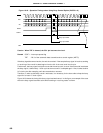
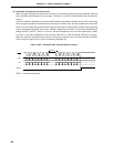
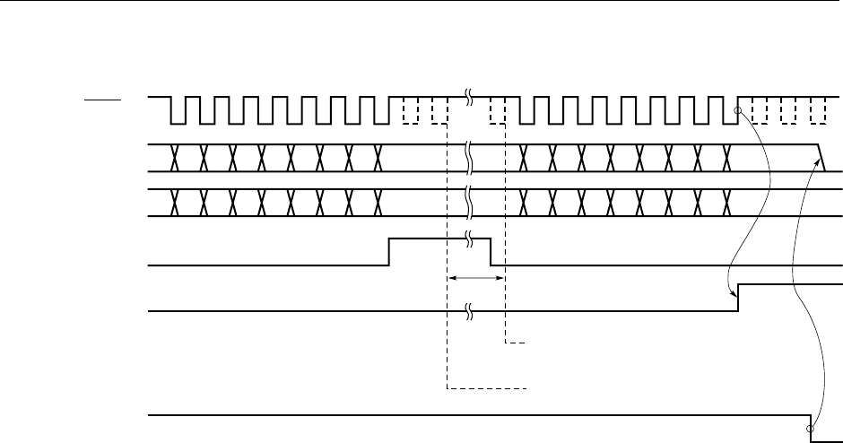
Figure 19-19. Operation Timings when Using Busy Control Option (BUSY0 = 0)
Caution When TRF is cleared, the SO1 pin becomes low level.
Remark CSIIF1 : Interrupt request flag
TRF : Bit 3 of the automatic data transmit/receive control register (ADTC)
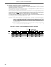
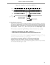
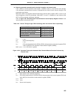
If the busy signal becomes inactive, the wait is canceled. If the sampled busy signal is inactive, sending
or receiving of the next 8 bit data begins from the fall of the next serial clock cycle.
Furthermore, the busy signal is asynchronous with the serial clock, so even if the slave side inactivates
the busy signal, it takes nearly 1 clock cycle at the most until it is sampled again. Also, it takes another
0.5 clock cycle after sampling until data transmission resumes.
Therefore, in order to definitely cancel a wait state, it is necessary for the slave side to keep the busy
signal for at least 1.5 clock cycles.
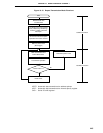
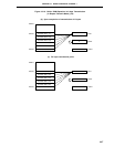
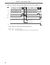
Figure 19-20 shows the timing of the busy signal and wait cancel. In this figure, an example of the case
where the busy signal becomes active when sending or receiving starts is shown.
SCK1
SO1 D7 D6 D5 D4 D3 D2 D1 D0 D7 D6 D5 D4 D3 D2 D1 D0
BUSY
CSIIF1
SI1 D7 D6 D5 D4 D3 D2 D1 D0 D7 D6 D5 D4 D3 D2 D1 D0
TRF
Busy Input Valid
Busy Input Clear
Wait