


444
CHAPTER 19 SERIAL INTERFACE CHANNEL 1
(c) Repeat transmission mode
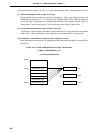
In this mode, data stored in the buffer RAM is transmitted repeatedly.
Serial transfer is started by writing any data to serial I/O shift register 1 (SIO1) when 1 is set in bit 7
(CSIE1) of the serial operating mode register 1 (CSIM1).
Unlike the basic transmission mode, after the last byte (data in address FAC0H) has been transmitted,
the interrupt request flag (CSIIF1) is not set, the value at the time when the transmission was started
is set in the automatic data transmit/receive address pointer (ADTP) again, and the buffer RAM contents
are transmitted again.
When a reception operation, busy control and strobe control are not performed, the P20/SI1, P23/STB
and P24/BUSY pins can be used as ordinary input/output ports.
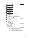
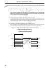
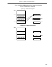
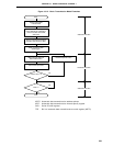
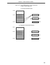
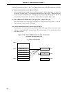
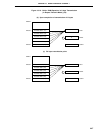
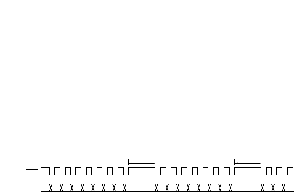
The repeat transmission mode operation timing is shown in Figure 19-14, and the operation flowchart
in Figure 19-15. Figure 19-16 shows an example of the buffer RAM operation in 6-byte repeat
transmission.
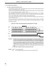
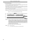
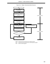
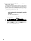
Figure 19-14. Repeat Transmission Mode Operation Timing
Caution Since, in the repeat transmission mode, a read is performed on the buffer RAM after
the transmission of one byte, the interval is included in the period up to the next
transmission. As the buffer RAM read is performed at the same time as CPU processing,
the maximum interval is dependent upon the CPU operation and the value of the
automatic data transmit/receive interval specify register (ADTI) (see (5) Automatic
transmit/receive interval time).
D7 D6 D5 D4 D3 D2 D1 D0 D7 D6 D5 D4 D3 D2 D1 D0
Interval Interval
D7 D6 D5
SCK1
SO1