


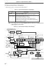

412
CHAPTER 18 SERIAL INTERFACE CHANNEL 0 (
µ
PD78078Y Subseries)
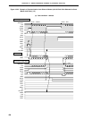
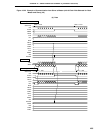
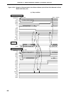
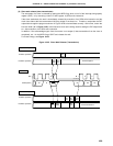
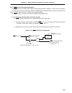
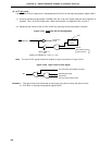
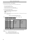
• Example of program releasing serial transfer status
SET1 P2.5 ; <1>
SET1 PM2.5 ; <2>
SET1 PM2.7 ; <3>
CLR1 CSIE0 ; <4>
SET1 CSIE0 ; <5>
SET1 RELT ; <6>
CLR1 PM2.7 ; <7>
CLR1 P2.5 ; <8>
CLR1 PM2.5 ; <9>
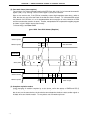
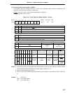
<1> Prevents the SDA0 pin from outputting a low level when the I
2
C bus mode is restored by the instruction in
<5>. The output of the SDA0 pin goes into a high-impedance state.
<2> Sets the P25 (/SDA0) pin in the input mode to prevent the SDA0 line from being affected when the port
mode is set by the instruction in <4>. The P25 pin is set in the input mode when the instruction in <2> is
executed.
<3> Sets the P27 (/SCL) pin in the input mode to prevent the SCL line from being affected when the port mode
is set by the instruction in <4>. The P27 pin is set in the input mode when the instruction in <3> is executed.
<4> Changes the mode from the I
2
C bus mode to port mode.
<5> Restores the mode from the port mode to the I
2
C bus mode.
<6> Prevents the instruction in <8> from causing the SDA0 pin to output a low level.
<7> Sets the P27 pin in the output mode because the P27 pin must be in the output mode in the I
2
C bus mode.
<8> Clears the output latch of the P25 pin to 0 because the output latch of the P25 pin must be cleared to 0 in
the I
2
C bus mode.
<9> Sets the P25 pin in the output mode because the P25 pin must be in the output mode in the I
2
C bus mode.
Remark RELT: bit 0 of serial bus interface control register (SBIC)