


298
CHAPTER 15 A/D CONVERTER
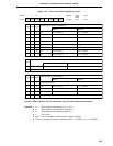
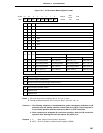
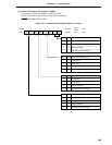
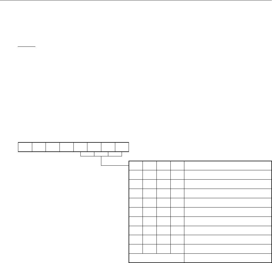
(2) A/D converter input select register (ADIS)
This register determines whether the ANI0/P10 to ANI7/P17 pins should be used for analog input channels
or ports. Pins other than those selected as analog input can be used as input/output ports.
ADIS is set with an 8-bit memory manipulation instruction.
RESET input sets ADIS to 00H.
Cautions 1. Set the analog input channel in the following order.
(1) Set the number of analog input channels with ADIS.
(2) Using the A/D converter mode register (ADM), select one channel to undergo A/D
conversion from among the channels set for analog input with ADIS.
2. No on-chip pull-up resistor can be used for the channels set for analog input with ADIS,
irrespective of the value of bit 1 (PUO1) of the pull-up resistor option register L (PUOL).
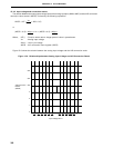
Figure 15-3. A/D Converter Input Select Register Format
0
7
0
6
00
4
ADIS3
3210
FF84H
Address
ADIS
Symbol
ADIS2 ADIS1 ADIS0
5
00H
After
Reset
R/W
R/W
ADIS3
0
0
0
0
0
0
0
0
1
Other than above
Number of Analog Input Channel Selection
No analog input channel (P10 to P17)
1 channel (ANI0, P11 to P17)
2 channel (ANI0, ANI1, P12 to P17)
3 channel (ANI0 to ANI2, P13 to P17)
4 channel (ANI0 to ANI3, P14 to P17)
5 channel (ANI0 to ANI4, P15 to P17)
6 channel (ANI0 to ANI5, P16, P17)
7 channel (ANI0 to ANI6, P17)
8 channel (ANI0 to ANI7)
Setting prohibited
ADIS2
0
0
0
0
1
1
1
1
0
ADIS1
0
0
1
1
0
0
1
1
0
ADIS0
0
1
0
1
0
1
0
1
0