


151
CHAPTER 6 PORT FUNCTIONS
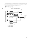
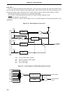
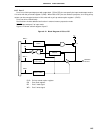
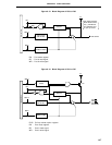
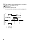
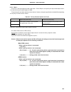
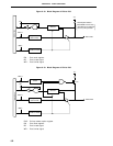
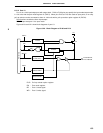
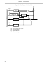
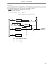
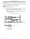
6.2.11 Port 9
Port 9 is an 7-bit input/output port with output latch. P90 to P96 pins can specify the input mode/output mode in
1-bit units with the port mode register 9 (PM9).
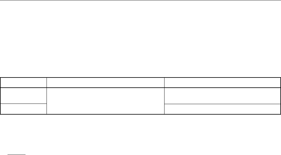
This port has pull-up resistor options as shown below. However, the option specification method differs depending
on the port pin and the device version.
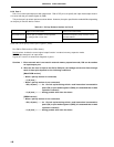
Table 6-5. Pull-up Resistor Options for Port 9
Higher 3 bits (P94 to P97) Lower 4 bits (P90 to P93)
Mask ROM version Internal pull-up resistors can be specified Internal mask-option pull-up resistors can be
by setting PUO6 in 3-bit units. specified bitwise.
PROM version No pull-up resistor options
PUO9 : Bit 1 of the pull-up resistor option register H (PUOH)
Pins P90 to P93 can drive LEDs directly.
Dual-functions include the control signal output function in external memory expansion mode.
RESET input sets port 6 to input mode.
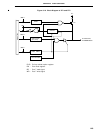
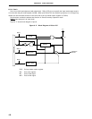
Figures 6-18 and 6-19 show block diagrams of port 9.
Caution When the low level is input to the P90 to P93 pins, the leakage current that flows through each
of these pins depends on the following conditions:
[Mask ROM version]
• When a pull-up resistor is connected,
–3
µ
A (max.)
• When a pull-up resistor is not connected,
–200
µ
A (max.) ........ for 1.5 clock cycles during which a read instruction is executed to
port 9 (P9) or port mode register 9 (PM9) (It is assumed that no wait
cycles are inserted.)
–3
µ
A (max.) ............ during periods other than the above
[PROM version]
• When a pull-up resistor is not connected,
–200
µ
A (max.) ........ for 1.5 clock cycles during which a read instruction is executed to
port 9 (P9) or port mode register 9 (PM9) (It is assumed that no wait
cycles are inserted.)
–3
µ
A (max.) ............ during periods other than the above