


280
CHAPTER 12 WATCHDOG TIMER
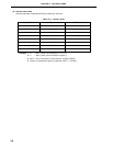
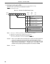
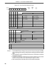
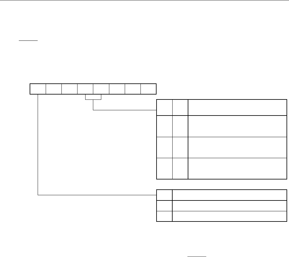
(2) Watchdog timer mode register (WDTM)
This register sets the watchdog timer operating mode and enables/disables counting.
WDTM is set with a 1-bit or 8-bit memory manipulation instruction.
RESET input sets WDTM to 00H.
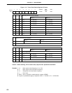
Figure 12-3. Watchdog Timer Mode Register Format
Notes 1. Once set to 1, WDTM3 and WDTM4 cannot be cleared to 0 by software.
2. Operation as an interval timer is started as soon as is set to 1.
3. Once set to 1, RUN cannot be cleared to 0 by software.
Thus, once counting starts, it can only be stopped by RESET input.
Cautions 1. When 1 is set in RUN so that the watchdog timer is cleared, the actual overflow time
is up to 0.5 % shorter than the time set by timer clock select register 2 (TCL2).
2. When using the watchdog timer modes 1 and 2, be sure that the interrupt request flag
(TMIF4) is 0 before setting WDTM4 to 1. If WDTM4 is set to 1 while TMIF4 is 1, a non-
maskable interrupt requests generated regardless of the contents of WDTM3.
Remark x : Don’t care
RUM
<7>
0
6
0
WDTM4
4
WDTM3
3210
FFF9H
Address
WDTM
Symbol
000
5
00H
After
Reset
R/W
R/W
RUN
0
1
Watchdog Timer Operation Mode Selection
Note 3
Count stop
Counter is cleared and counting starts.
WDTM3
x
0
1
Watchdog Timer Operation Mode
Selection
Note 1
Interval timer mode
Note 2
(Maskable interrupt occurs upon
generation of an overflow.)
Watchdog timer mode 1
(Non-maskable interrupt occurs upon
generation of an overflow.)
Watchdog timer mode 2
(Reset operation is activated upon
generation of an overflow.)
WDTM4
0
1
1