


282
CHAPTER 12 WATCHDOG TIMER
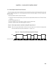
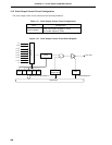
12.4.2 Interval timer operation
The watchdog timer operates as an interval timer which generates interrupt requests repeatedly at an interval
of the preset count value when bit 4 (WDTM4) of the watchdog timer mode register (WDTM) is set to 0, respectively.
The count clock (interval time) can be selected with bits 0 to 2 (TCL20 to TCL22) of the timer clock select register
2 (TCL2). The watchdog timer starts operation as an interval timer when bit 7 (RUN) of WDTM is set to 1.
When the watchdog timer operated as interval timer, the interrupt mask flag (TMMK4) and priority specify flag
(TMPR4) are validated and the maskable interrupt request (INTWDT) can be generated. Among maskable interrupt
requests, the INTWDT default has the highest priority.
The interval timer continues operating in the HALT mode but it stops in STOP mode. Thus, set bit 7 (RUN) of
WDTM to 1 before the STOP mode is set, clear the interval timer and then execute the STOP instruction.
Cautions 1. Once bit 4 (WDTM4) of WDTM is set to 1 (with the watchdog timer mode selected), the interval
timer mode is not set unless RESET input is applied.
2. The interval time just after setting with WDTM may be shorter than the set time by a maximum
of 0.5 %.
3. When the subsystem clock is selected for CPU clock, watchdog timer count operation is
stopped.
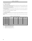
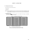
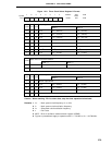
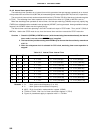
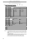
Table 12-5. Interval Timer Interval Time
TCL22 TCL21 TCL20 Interval Time MCS = 1 MCS = 0
000 2
11
x 1/fXX 2
11
x 1/fX (410
µ
s) 2
12
x 1/fX (819
µ
s)
001 2
12
x 1/fXX 2
12
x 1/fX (819
µ
s) 2
13
x 1/fX (1.64 ms)
010 2
13
x 1/fXX 2
13
x 1/fX (1.64 ms) 2
14
x 1/fX (3.28 ms)
011 2
14
x 1/fXX 2
14
x 1/fX (3.28 ms) 2
15
x 1/fX (6.55 ms)
100 2
15
x 1/fXX 2
15
x 1/fX (6.55 ms) 2
16
x 1/fX (13.1 ms)
101 2
16
x 1/fXX 2
16
x 1/fX (13.1 ms) 2
17
x 1/fX (26.2 ms)
110 2
17
x 1/fXX 2
17
x 1/fX (26.2 ms) 2
18
x 1/fX (52.4 ms)
111 2
19
x 1/fXX 2
19
x 1/fX (104.9 ms) 2
20
x 1/fX (209.7 ms)
Remarks 1. f
XX : Main system clock frequency (fX or fX/2)
2. fX : Main system clock oscillation frequency
3. MCS : Bit 0 of oscillation mode selection register (OSMS)
4. TCL20 to TCL22 : Bits 0 to 2 of timer clock select register 2 (TCL2)
5. Figures in parentheses apply to operation with f
X = 5.0 MHz.