


253
CHAPTER 10 8-BIT TIMER/EVENT COUNTERS 5 AND 6
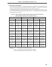
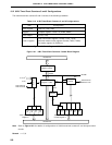
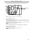
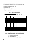
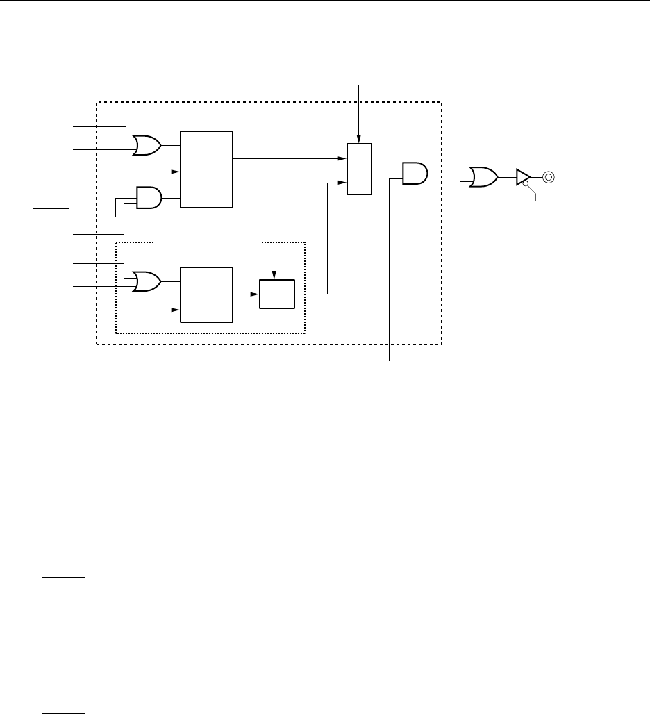
Figure 10-2. Block Diagram of 8-Bit Timer/Event Counters 5 and 6 Output Control Circuit
Remarks 1. The section in the broken line is an output control circuit.
2. n = 5, 6
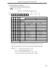
(1) Compare register 50 and 60 (CR50, 60)
These 8-bit registers compare the value set to CR50 to 8-bit timer register 5 (TM5) count value, and the
value set to CR60 to the 8-bit timer register 6 (TM6) count value, and, if they match, generate interrupts
request (INTTM5 and INTTM6, respectively).
CR50 and CR60 are set with an 8-bit memory manipulation instruction. They cannot be set with a 16-bit
memory manipulation instruction. The 00H to FFH values can be set.
RESET input sets CR50 and CR60 values to 00H.
Caution To use PWM mode, set CRn0 value before setting TMCn (n = 5, 6) to PWM mode.
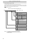
(2) 8-bit timer registers 5 and 6 (TM5, TM6)
These 8-bit registers count count pulses.
TM5 and TM6 are read with an 8-bit memory manipulation instruction.
RESET input sets TM5 and TM6 to 00H.
RESET
LVRn
LVSn
TMCn1
TMCn6
OVFn
INTTMn
TCEn
INTTMn
R
S
Q
PWM Output Circuit
Timer Output F/F2
Level
F/F
R
S
INV
Q
TMCn1 TMCn6
Selector
P100, P101
Output Latch
PM100,
PM101
TO5/P100/TI5,
TO6/P101/TI6
TOEn