


418
CHAPTER 19 SERIAL INTERFACE CHANNEL 1
19.3 Serial Interface Channel 1 Control Registers
The following four types of registers are used to control serial interface channel 1.
• Timer clock select register 3 (TCL3)
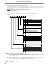
• Serial operating mode register 1 (CSIM1)
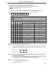
• Automatic data transmit/receive control register (ADTC)
• Automatic data transmit/receive interval specify register (ADTI)
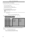
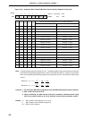
(1) Timer clock select register 3 (TCL3)
This register sets the serial clock of serial interface channel 1.
TCL3 is set with an 8-bit memory manipulation instruction.
RESET input sets TCL3 to 88H.
Remark Besides setting the serial clock of serial interface channel 1, TCL3 sets the serial clock of serial
interface channel 0.
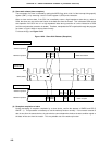
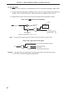
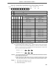
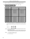
Figure 19-2. Timer Clock Select Register 3 Format
Caution When rewriting other data to TCL3, stop the serial transfer operation beforehand.
Remarks 1. f
XX : Main system clock frequency (fX or fX/2)
2. fX : Main system clock oscillation frequency
3. MCS : Bit 0 of oscillation mode selection register (OSMS)
4. Figures in parentheses apply to operation with f
X = 5.0 MHz.
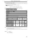
Serial Interface Channel 1 Serial Clock Selection
TCL37 TCL36 TCL35 TCL34
0
0
1
1
1
1
1
1
1
1
0
0
0
0
1
1
1
1
0
0
1
1
0
0
0
1
0
1
0
1
0
1
f
XX
/2
f
XX
/2
2
f
XX
/2
3
f
XX
/2
4
f
XX
/2
5
f
XX
/2
6
f
XX
/2
7
f
XX
/2
8
MCS = 1
Setting prohibited
f
X
/2
2
(1.25 MHz)
f
X
/2
3
(625 kHz)
f
X
/2
4
(313 kHz)
f
X
/2
5
(156 kHz)
f
X
/2
6
(78.1 kHz)
f
X
/2
7
(39.1 kHz)
f
X
/2
8
(19.5 kHz)
MCS = 0
f
X
/2
2
(1.25 MHz)
f
X
/2
3
(625 kHz)
f
X
/2
4
(313 kHz)
f
X
/2
5
(156 kHz)
f
X
/2
6
(78.1 kHz)
f
X
/2
7
(39.1 kHz)
f
X
/2
8
(19.5 kHz)
f
X
/2
9
(9.8 kHz)
Other than above Setting prohibited
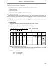
65432107Symbol
TCL3 TCL37 TCL36 TCL35 TCL34 TCL33 TCL32 TCL31 TCL30
FF43H 88H R/W
Address After Reset R/W