


296
CHAPTER 15 A/D CONVERTER
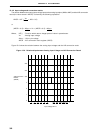
Caution A series resistor string of approximately 10 kΩ is connected between AVREF0 pin and AVSS
pin. Therefore, if the output impedance of the reference voltage source is high, AVREF0 pin
is connected in parallel with the series resistor string between AV
REF0 pin and AVSS pin. As
a result, the reference voltage error will increase.
(8) AV
SS pin
This is a GND potential pin of the A/D converter. Keep it at the same potential as the VSS pin when not using
the A/D converter.
(9) AV
DD pin
This is an A/D converter analog power supply pin. Keep it at the same potential as the VSS pin when not
using the A/D converter.
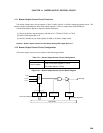
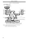
15.3 A/D Converter Control Registers
The following three types of registers are used to control the A/D converter.
• A/D converter mode register (ADM)
• A/D converter input select register (ADIS)
• External interrupt mode register 1 (INTM1)
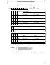
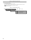
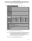
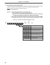
(1) A/D converter mode register (ADM)
This register sets the analog input channel for A/D conversion, conversion time, conversion start/stop and
external trigger.
ADM is set with a 1-bit or 8-bit memory manipulation instruction.
RESET input sets ADM to 01H.