


550
CHAPTER 24 STANDBY FUNCTION
24.2.2 STOP mode
(1) STOP mode set and operating status
The STOP mode is set by executing the STOP instruction. It can be set only with the main system clock.
Cautions 1. When the STOP mode is set, the X2 pin is internally connected to V
DD via a pull-up
resistor to minimize leakage current at the crystal oscillator. Thus, do not use the STOP
mode in a system where an external clock is used for the main system clock.
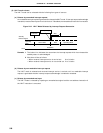
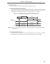
2. Because the interrupt request signal is used to release the standby mode, if there is
an interrupt source with the interrupt request flag set and the interrupt mask flag reset,
the standby mode is immediately cleared if set. Thus, the STOP mode is reset to the
HALT mode immediately after execution of the STOP instruction. After the wait set
using the oscillation stabilization time select register (OSTS), the operating mode is set.
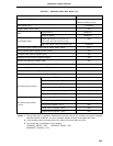
The operating status in the STOP mode is described below.
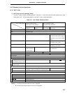
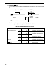
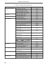
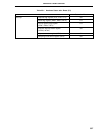
Table 24-3. STOP Mode Operating Status
STOP Mode Setting
With Subsystem Clock Without Subsystem Clock
Item
Clock Generator Only main system clock stops oscillation.
CPU Operation stops.
Port (output latch) Status before STOP mode setting is held.
16-bit timer/event counter Operable when watch timer output is used Operation stops.
as count clock (fXT is selected as count
clock for watch timer).
8-bit timer/event counters 1 and 2
Operable when TI1 or TI2 is selected for the count clock.
8-bit timer/event counters 5 and 6
Operable when TI5 or TI6 is selected for the count clock.
Watch timer Operable when fXT is selected for the count clock. Operation stops.
Watchdog timer Operation stops.
A/D converter Operation stops.
D/A converter Operable.
Real-time output port Operable when external trigger is used, or TI1 or TI2 is selected for the 8-bit timer/
event counter 1 or 2 count clock.
Serial Interface
When a function
other than
auto
Operable only when externally supplied clock is specified as the serial clock.
transmit/receive & UART is used
When auto transmit/receive Operation stops.
function or UART is used
External interrupt
INTP0 Operation disabled.
INTP1 to INTP6 Operable.
Bus lines in external expansion
AD0 to AD7 Enters high-impedance state.
A0 to A15 Holds the state before STOP mode is set.
ASTB Outputs low level.
WR, RD Outputs high level.
WAIT Enters high-impedance state.