


188
CHAPTER 8 16-BIT TIMER/EVENT COUNTER
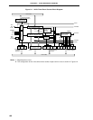
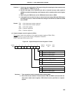
(1) Capture/compare register 00 (CR00)
CR00 is a 16-bit register which has the functions of both a capture register and a compare register. Whether
it is used as a capture register or as a compare register is set by bit 0 (CRC00) of capture/compare control
register 0 (CRC0).
When CR00 is used as a compare register, the value set in the CR00 is constantly compared with the 16-
bit timer register (TM0) count value, and an interrupt request (INTTM00) is generated if they match. CR00
is used as a register to hold the interval time when TM0 is set to interval timer operation, and it is used as
a register to set the pulse width when TM0 is set to the PWM output operation.
When CR00 is used as a capture register, it is possible to select the valid edge of the INTP0/TI00 pin or
the INTP1/TI01 pin as the capture trigger. The INTP0/TI00 or INTP1/TI01 valid edge is set by means of
external interrupt mode register 0 (INTM0).
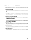
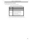
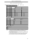
If CR00 is specified as a capture register and capture trigger is specified to be the valid edge of the INTP0/
TI00 pin, the situation is as shown in the following table.
Table 8-5. INTP0/TI00 Pin Valid Edge and CR00 Capture Trigger Valid Edge
ES11 ES10 INTP0/TI00 Pin Valid Edge CR00 Capture Trigger Valid Edge
0 0 Falling edge Rising edge
0 1 Rising edge Falling edge
1 0 Setting prohibited
1 1 Both rising and falling edges No capture operation
CR00 is set by a 16-bit memory manipulation instruction.
After RESET input, the value of CR00 is undefined.
Cautions 1. Set the PWM data (14 bits) to the higher 14 bits of CR00 and set 00 to the lower 2 bits.
2. Set values other than 0000H to CR00. Therefore, when used as an event counter, 1-pulse
count operation cannot be executed.
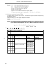
3. When the value after CR00 is changed is smaller than the 16-bit timer register (TM0)
value, TM0 continues to count, overflows, and resumes counting from zero. Therefore,
when the value after CR00 is changed (M) is smaller than the value before CR00 is
changed (N), it is necessary to restart the timer after changing CR00.
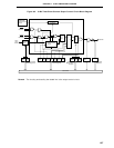
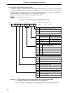
(2) Capture/compare register 01 (CR01)
CR01 is a 16-bit register which has the functions of both a capture register and a compare register. Whether
it is used as a capture register or a compare register is set by bit 2 (CRC02) of capture/compare control
register 0.
When CR01 is used as a compare register, the value set in the CR01 is constantly compared with the 16-
bit timer register (TM0) count value, and an interrupt request (INTTM01) is generated if they match.
When CR01 is used as a capture register, it is possible to select the valid edge of the INTP0/TI00 pin as
the capture trigger. Setting of the INTP0/TI00 valid edge is set by means of external interrupt mode register
0 (INTM0).
CR01 is set with a 16-bit memory manipulation instruction.
After RESET input, the value of CR01 is undefined.
Caution If a valid edge of TI0/P00 pin is input while reading out CR01, CR01 does not carry out
capture operation and retains the data. However, the interrupt request flag (PIF0) is set
by the detection of a valid edge.