


206
CHAPTER 8 16-BIT TIMER/EVENT COUNTER
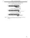
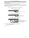
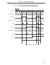
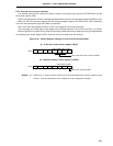
(2) Two pulse width measurements with free-running counter
When the 16-bit timer register (TM0) is operated in free-running mode (see register settings in Figure 8-
20), it is possible to simultaneously measure the pulse widths of the two signals input to the TI00/P00 pin
and the TI01/P01 pin.
When the edge specified by bits 2 and 3 (ES10 and ES11) of external interrupt mode register 0 (INTM0)
is input to the TI00/P00 pin, the value of TM0 is taken into 16-bit capture/compare register 01 (CR01) and
an external interrupt request signal (INTP0) is set.
Also, when the edge specified by bits 4 and 5 (ES20 and ES21) of INTM0 is input to the TI01/P01 pin, the
value of TM0 is taken into 16-bit capture/compare register 00 (CR00) and an external interrupt request signal
(INTP1) is set.
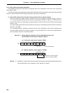
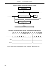
Any of three edge specifications can be selected-rising, falling, or both edges-as the valid edges for the TI00/
P00 pin and the TI01/P01 pin by means of bits 2 and 3 (ES10 and ES11) and bits 4 and 5 (ES20 and ES21)
of INTM0, respectively.
For TI00/P00 pin valid edge detection, sampling is performed at the interval selected by means of the
sampling clock selection register (SCS), and a capture operation is only performed when a valid level is
detected twice, thus eliminating noise with a short pulse width.
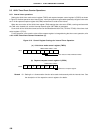
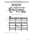
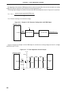
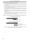
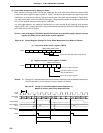
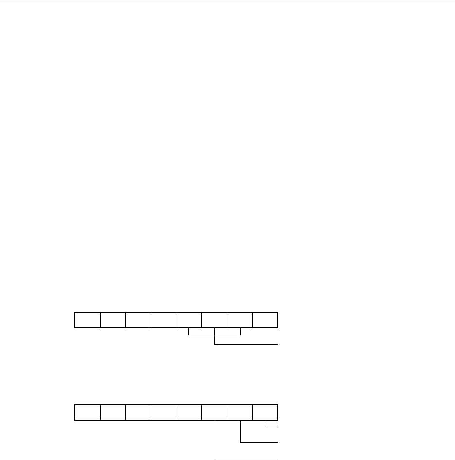
Figure 8-20. Control Register Settings for Two Pulse Width Measurements with Free-Running Counter
(a) 16-bit timer mode control register (TMC0)
(b) Capture/compare control register 0 (CRC0)
Remark 0/1: Setting 0 or 1 allows another function to be used simultaneously with pulse width measurement.
See the description of the respective control registers for details.
TMC0 00/1100000
OVF0TMC01TMC02TMC03
Free-Running Mode
CRC0 10100000
CRC00CRC01CRC02
CR00 set as capture register
Captured in CR00 on valid edge of TI01/P01 Pin
CR01 set as capture register