


262
CHAPTER 10 8-BIT TIMER/EVENT COUNTERS 5 AND 6
10.4.3 Square-wave output
A square wave with any selected frequency is output at intervals of the value preset to 8-bit compare registers
(CR50 and CR60).
The TO5/P100/TI5 or TO6/P101/TI6 pin output status is reversed at intervals of the count value preset to CR50
or CR60 by setting bit 1 (TMC51) and bit 0 (TOE5) of the 8-bit timer output control register 5 (TMC5), or bit 1 (TMC61)
and bit 0 (TOE1) of the 8-bit timer mode control register 6 (TMC6) to 1.
This enables a square wave of any selected frequency to be output.
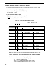
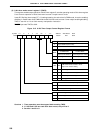
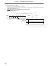
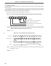
Figure 10-12. 8-Bit Timer Mode Control Register Settings for Square-Wave Output Operation
Caution When TI5/P100/TO5 or TI6/P101/TO6 pin is used as the timer output, set port mode register
(PM100 or PM101) and output latch (P100 or P101) to 0.
Remark n = 5, 6
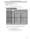
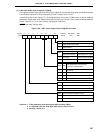
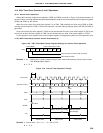
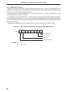
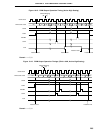
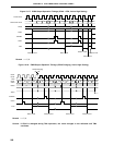
Figure 10-13. Timing of Square Wave Output Operation
Note The initial value of the TOn output can be set by bits 2 and 3 (LVSn and LVRn) of the 8-bit timer output
control register n (TOCn).
Remark n = 5, 6
1
TCEn
0
TMCn6
0 0 0/1
LVSn LVRn TMCn1 TOEn
TMCn
0/1 1 1
TOn output enable
Inversion of output on match of TMn and CRn0
Specifies TO0 output F/F1 initial value
Clear and start mode on match of TMn and CRn0
TMn operation enable
Count Clock
TMn Count Value 01 0200 N–1 N 00 01 02 N–1 N 00
Count Start
CRn0 N N
TOn
Note