


546
CHAPTER 24 STANDBY FUNCTION
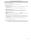
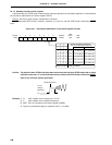
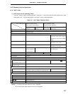
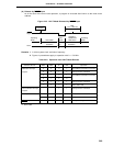
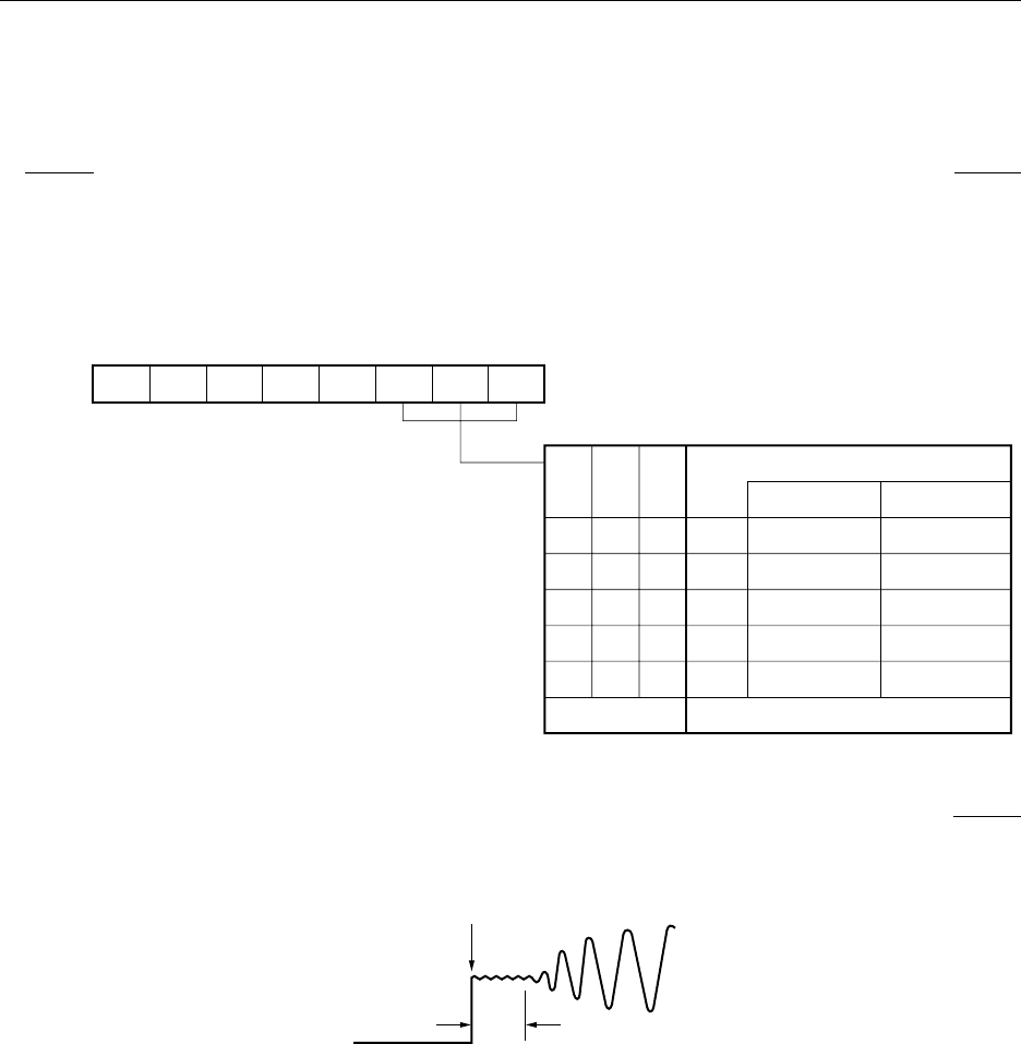
24.1.2 Standby function control register
A wait time after the STOP mode is cleared upon interrupt request till the oscillation stabilizes is controlled with
the oscillation stabilization time select register (OSTS).
OSTS is set with an 8-bit memory manipulation instruction.
RESET input sets OSTS to 04H. However, it takes 2
17
/fX, not 2
18
/fX, until the STOP mode is cleared by RESET
input.
Figure 24-1. Oscillation Stabilization Time Select Register Format
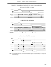
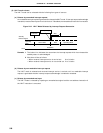
Caution The wait time after STOP mode clear does not include the time from STOP mode clear to clock
oscillation start (see “a” in the illustration below), whether the STOP mode is cleared by RESET
input or by interrupt request generation.
Remarks 1. f
XX :Main system clock frequency (fX or fX/2)
2. f
X :Main system clock oscillation frequency
3. MCS :Bit 0 of oscillation mode select register (OSMS)
4. Figures in parentheses apply to operation with fX = 5.0 MHz.
STOP Mode Clear
X1 Pin
Voltage
Waveform
V
SS
a
Address
FFFAH 04H
After
Reset
R/W
R/W
0
0
0
0
1
Selection of Oscillation Stabilization
Time wnen STOP Mode is Released
2
12
/f
xx
2
14
/f
xx
2
15
/f
xx
2
16
/f
xx
2
17
/f
xx
OSTS2
7
0
Symbol
OSTS
6
0
5
0
4
0
3
0
2
OSTS2
1
OSTS1
0
OSTS0
0
0
1
1
0
Other than above
OSTS1
MCS = 1 MCS = 0
2
12
/f
x
(819 s)
2
14
/f
x
(3.28 ms)
2
15
/f
x
(6.55 ms)
2
16
/f
x
(13.1 ms)
2
17
/f
x
(26.2 ms)
2
13
/f
x
(1.64 ms)
2
15
/f
x
(6.55 ms)
2
16
/f
x
(13.1 ms)
2
17
/f
x
(26.2 ms)
2
18
/f
x
(52.4 ms)
µ
0
1
0
1
0
OSTS0
Setting prohibited