


357
CHAPTER 17 SERIAL INTERFACE CHANNEL 0 (
µ
PD78078 SUBSERIES)
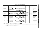
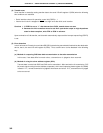
(d) For pins which are to be used for data input/output, be sure to carry out the following settings before
serial transfer of the 1st byte after RESET input.
<1> Set 1 to the output latch of P25 and P26
<2> Set 1 to bit 0 (RELT) of the serial bus interface control register (SBIC).
<3> Set 0 to the output latch of P25 and P26, to which 1 has been set.
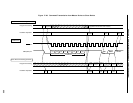
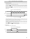
(e) If the SB0 (SB1) line changes from low level to high level or from high level to low level while the SCK0
line is at high level, it is recognized as either a bus release signal or a command signal. Therefore,
if the changing timing of bus fluctuates because of the wiring capacitance, etc., this may be wrongly
interpreted as a bus release signal (or a command signal) even while data is being transmitted. Care
should be taken in the wiring.
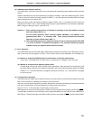
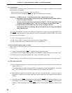
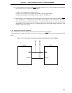
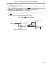
17.4.4 2-wire serial I/O mode operation
The 2-wire serial I/O mode can cope with any communication format by program.
Communication is basically carried out with two lines of serial clock (SCK0) and serial data input/output (SB0
or SB1).
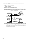
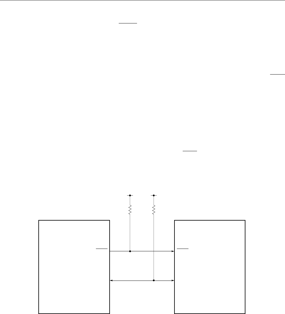
Figure 17-31. Serial Bus Configuration Example Using 2-Wire Serial I/O Mode
Master
SCK0
Slave
SB0 (SB1)
SCK0
SB0 (SB1)
V
DD
V
DD