


458
CHAPTER 20 SERIAL INTERFACE CHANNEL 2
20.2 Serial Interface Channel 2 Configuration
Serial interface channel 2 consists of the following hardware.
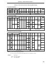
Table 20-1. Serial Interface Channel 2 Configuration
Item Configuration
Register Transmit shift register (TXS)
Receive shift register (RXS)
Receive buffer register (RXB)
Control register Serial operating mode register 2 (CSIM2)
Asynchronous serial interface mode register (ASIM)
Asynchronous serial interface status register (ASIS)
Baud rate generator control register (BRGC)
Port mode register 7 (PM7)
Note
Note Refer to Figure 6-15 Block Diagram of P70 and Figure 6-16 Block Diagram of P71 and
P72.
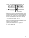
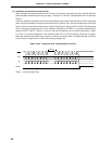
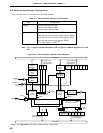
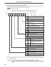
Figure 20-1. Serial Interface Channel 2 Block Diagram
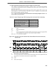
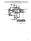
Note See Figure 20-2 for the baud rate generator configuration.
Internal Bus
RXE PS1 PS0
Asynchronous
Serial Interface
Mode Register
CL SL ISRMTXE SCK
PE FE
OVE
Asynchronous
Serial Interface
Status Register
Direction
Control
Circuit
Transmit
Shift Register
(TXS/SIO2)
Receive Buffer
Register
(RXB/SIO2)
Direction
Control
Circuit
Receive
Shift Register
(RXS)
Reception
Control
Circuit
Transmission
Control
Circuit
RxD/SI2
/P70
TxD/SO2
/P71
PM71
INTSR/INTCSI2
ISRM
ASCK/SCK2
/P72
CSIE2
CSIM
22
CSCK
INTSER
SCK Output
Control Circuit
Baud Rate Generator
f
xx
to
f
xx
/2
10
MDL3 MDL2 MDL1 MDL0
4
Internal Bus
TPS3 TPS2 TPS1 TPS0
4
CSCK
SCK
CSIE2
TXE
RXE
INTST
Baud Rate Generator
Control Register
Note
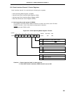
Serial Operating
Mode Register 2
PM72