


220
CHAPTER 8 16-BIT TIMER/EVENT COUNTER
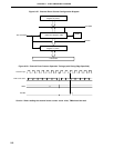
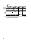
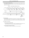
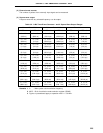
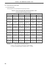
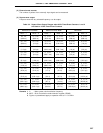
(4) Capture register data retention timings
If the valid edge of the TI00/P00 pin is input during 16-bit capture/compare register 01 (CR01) read, CR01
holds data without carrying out capture operation. However, the interrupt request flag (PIF0) is set upon
detection of the valid edge.
Figure 8-37. Capture Register Data Retention Timing
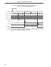
(5) Valid edge setting
Set the valid edge of the TI00/P00/INTP0 pin after setting bits 1 to 3 (TMC01 to TMC03) of the 16-bit timer
mode control register (TMC0) to 0, 0 and 0, respectively, and then stopping timer operation. Valid edge
setting is carried out with bits 2 and 3 (ES10 and ES11) of the external interrupt mode register 0 (INTM0).
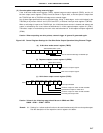
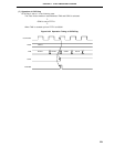
(6) Re-trigger of one-shot pulse
(a) One-shot pulse output using software
When outputting one-shot pulse, do not set 1 in OSPT. When outputting one-shot pulse again, execute
it after the INTTM00, which is the match interrupt request with CR00, is generated.
(b) One-shot pulse output using external trigger
When outputting one-shot pulses, external trigger is ignored if generated again.
Count Pulse
TM0 Count Value
Edge Input
Interrupt
Request Flag
Capture Read Signal
CR01 Captured Value
Capture Operation
Ignored
XN + 1
N N + 1 N + 2 M M + 1 M + 2