


489
CHAPTER 20 SERIAL INTERFACE CHANNEL 2
SI2
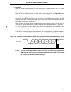
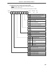
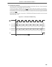
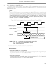
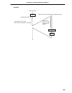
SCK2 12345678
DI7 DI6 DI5 DI4 DI3 DI2 DI1 DI0
SO2 DO7 DO6 DO5 DO4 DO3 DO2 DO1 DO0
SRIF
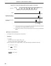
Transfer Start at the Falling Edge of SCK2
End of Transfer
(2) Communication operation
In the 3-wire serial I/O mode, data transmission/reception is performed in 8-bit units. Data is transmitted/
received bit by bit in synchronization with the serial clock.
Transmit shift register (TXS/SIO2) and receive shift register (RXS) shift operations are performed in
synchronization with the fall of the serial clock (SCK2). Then transmit data is held in the SO2 latch and output
from the SO2 pin. Also, receive data input to the SI2 pin is latched in the receive buffer register (RXB/SIO2)
on the rise of SCK2.
At the end of an 8-bit transfer, the operation of TXS/SIO2 and RXS stops automatically, and the interrupt
request flag (SRIF) is set.
Figure 20-12. 3-Wire Serial I/O Mode Timing