


230
CHAPTER 9 8-BIT TIMER/EVENT COUNTERS 1 AND 2
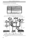
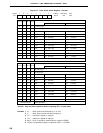
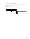
(1) Compare registers 10 and 20 (CR10, CR20)
These are 8-bit registers to compare the value set to CR10 to the 8-bit timer register 1 (TM1) count value,
and the value set to CR20 to the 8-bit timer register 2 (TM2) count value, and, if they match, generate an
interrupt request (INTTM1 and INTTM2, respectively).
CR10 and CR20 are set with an 8-bit memory manipulation instruction. They cannot be set with a 16-bit
memory manipulation instruction. When the compare register is used as 8-bit timer/event counter, the 00H
to FFH values can be set. When the compare register is used as 16-bit timer/event counter, the 0000H to
FFFFH values can be set.
RESET input makes CR10 and CR20 undefined.
Caution When using the compare register as 16-bit timer/event counter, be sure to set data after
stopping timer operation.
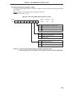
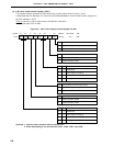
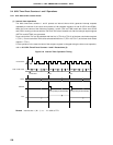
(2) 8-bit timer registers 1, 2 (TM1, TM2)
These are 8-bit registers to count count pulses.
When TM1 and TM2 are used in the 8-bit timer x 2-channel mode, they are read with an 8-bit memory
manipulation instruction. When TM1 and TM2 are used as 16-bit timer x 1-channel mode, 16-bit timer register
(TMS) is read with a 16-bit memory manipulation instruction.
RESET input sets TM1 and TM2 to 00H.