


449
CHAPTER 19 SERIAL INTERFACE CHANNEL 1
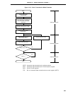
(4) Synchronization control
Busy control and strobe control are functions for synchronizing sending and receiving between the master
device and slave device.
By using these functions, it is possible to detect bit slippage during sending and receiving.
(a) Busy control option
Busy control is a function which causes the master device’s serial transmission to wait when the slave
device outputs a busy signal to the master device, and maintain the wait state while that busy signal
is active.
When the busy control option is used, the conditions shown below are necessary.
• Bit 5 (ATE) of serial operation mode register 1 (CSIM1) should be set at (1).
• Bit 1 (BUSY1) of the automatic data transmit/receive control register (ADTC) should be set at (1).
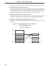
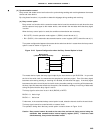
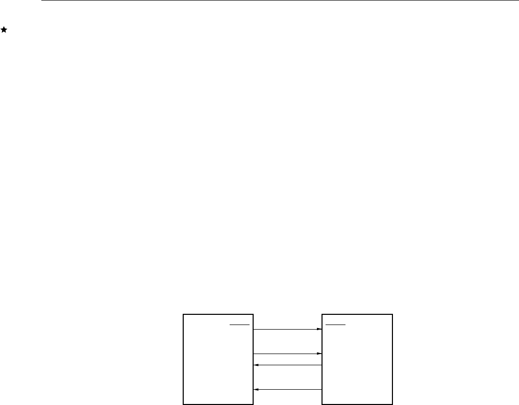
The system configuration between the master device and slave device in cases where the busy control
option is used is shown in Figure 19-18.
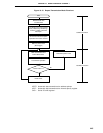
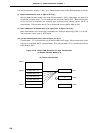
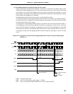
Figure 19-18. System Configuration when the Busy Control Option is Used
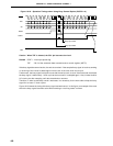
The master device inputs the busy signal output by the slave device to pin BUSY/P24. In sync with
the fall of the serial clock, the master device samples the input busy signal. Even if the busy signal
becomes active during sending or receiving of 8 bit data, the wait does not apply. If the busy signal
becomes active at the rise of the serial clock 2 clock cycles after sending or receiving of 8 bit data ends,
the busy input first becomes effective at that point, and thereafter, sending or receiving of data waits
during the period that the busy signal is active.
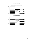
The busy signal’s active level is set in bit 0 (BUSY0) of ADTC.
BUSY0 = 0: Active high
BUSY0 = 1: Active low
Furthermore, in the case that the busy control option is used, select the internal clock for the serial clock.
The busy signal cannot be controlled with an external clock.
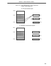
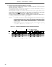
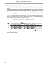
The operation timing when the busy control option is used is shown in Figure 19-19.
Caution Busy control cannot be used at the same time as interval timing control using the
automatic data transmit/receive interval specify register (ADTI). If both are used
simultaneously, busy control becomes invalid.
SCK1
SO1
SI1
SCK1
SO1
SI1
BUSY
Master Device
(µPD78078, 78078Y Subseries)
Slave Device