


228
CHAPTER 9 8-BIT TIMER/EVENT COUNTERS 1 AND 2
9.2 8-Bit Timer/Event Counters 1 and 2 Configurations
The 8-bit timer/event counters 1 and 2 consist of the following hardware.
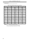
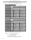
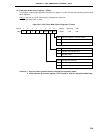
Table 9-5. 8-Bit Timer/Event Counters 1 and 2 Configurations
Item Configuration
Timer register 8 bits x 2 (TM1, TM2)
Register Compare register: 8 bits x 2 (CR10, CR20)
Timer output 2 (TO1, TO2)
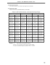
Timer clock select register 1 (TCL1)
8-bit timer mode control register 1 (TMC1)
8-bit timer output control register (TOC1)
Port mode register 3 (PM3)
Note
Note Refer to Figure 6-9 Block Diagram of P30 to P37.
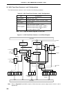
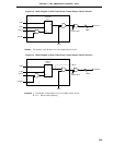
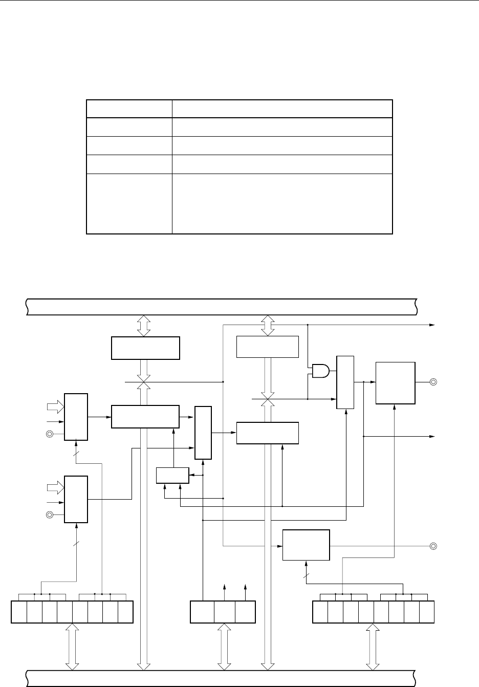
Figure 9-1. 8-Bit Timer/Event Counters 1 and 2 Block Diagram
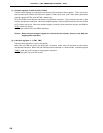
Note Refer to Figures 9-2 and 9-3 for details of 8-bit timer/event counter output control circuits 1 and 2,
respectively.
Control register
Internal Bus
8-Bit Compare
Register (CR10)
Match
8-Bit Timer
Register 1 (TM1)
Selector
Clear
Selector
Selector
TI1/P33
f
XX
/2 to f
XX
/2
9
f
XX
/2 to f
XX
/2
9
fXX/2
11
fXX/2
11
TI2/P34
4
4
8-Bit Timer
Mode Control
Register
TMC12 TCE2 TCE1
Internal Bus
LVS2 LVR2
TOC
15
TOE2LVS1 LVR1
TOC
11
TOE1
4
8-Bit Timer
Register 2 (TM2)
8-Bit Timer/
Event Counter
Output Control
Circuit
8-Bit Timer
Output Control
Register
8-Bit
Timer/Event
Counter
Output
Control
Selector
Clear
Match
8-Bit Compare
Register (CR20)
Note
INTTM1
TO2/P32
INTTM2
TO1/P31
Selector
TCL
17
TCL
16
TCL
15
TCL
14
TCL
13
TCL
12
TCL
11
TCL
10
Timer Clock
Select Register 1
Note