28
LIST OF FIGURES (8/9)
Figure No. Title Page
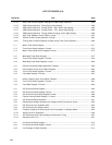
22-13 Interrupt Request Acknowledge Processing Algorithm............................................................. 517
22-14 Interrupt Request Acknowledge Timing (Minimum Time)......................................................... 518
22-15 Interrupt Request Acknowledge Timing (Maximum Time)........................................................ 518
22-16 Multiple Interrupt Example.......................................................................................................... 520
22-17 Interrupt Request Hold ............................................................................................................... 522
22-18 Basic Configuration of Test Function......................................................................................... 523
22-19 Format of Interrupt Request Flag Register 1L .......................................................................... 524
22-20 Format of Interrupt Mask Flag Register 1L ............................................................................... 524
22-21 Key Return Mode Register Format ............................................................................................ 525
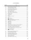
23-1 Memory Map when Using External Device Expansion Function ............................................. 529
23-2 Memory Expansion Mode Register Format ............................................................................... 531
23-3 Internal Memory Size Switching Register Format..................................................................... 532
23-4 External Bus Type Select Register Format ............................................................................... 533
23-5 Instruction Fetch from External Memory in Multiplexed Bus Mode ......................................... 535
23-6 External Memory Read Timing in Multiplexed Bus Mode......................................................... 536
23-7 External Memory Write Timing in Multiplexed Bus Mode......................................................... 537
23-8 External Memory Read Modify Write Timing in Multiplexed Bus Mode................................... 538
23-9 Instruction Fetch from External Memory in Separate Bus Mode ............................................. 540
23-10 External Memory Read Timing in Separate Bus Mode ............................................................ 541
23-11 External Memory Write Timing in Separate Bus Mode ............................................................ 542
23-12 External Memory Read Modify Write Timing in Separate Bus Mode ...................................... 543
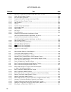
24-1 Oscillation Stabilization Time Select Register Format.............................................................. 546
24-2 HALT Mode Released by Interrupt Request Generation.......................................................... 548
24-3 HALT Mode Released by RESET Input .................................................................................... 549
24-4 STOP Mode Released by Interrupt Request Generation ......................................................... 551
24-5 STOP Mode Released by RESET Input.................................................................................... 552
25-1 Block Diagram of Reset Function .............................................................................................. 553
25-2 Timing of Reset by RESET Input............................................................................................... 554
25-3 Timing of Reset due to Watchdog Timer Overflow................................................................... 554
25-4 Timing of Reset by RESET Input in STOP Mode ..................................................................... 554
26-1 Block Diagram of ROM Correction ............................................................................................ 559
26-2 Correction Address Registers 0 and 1 Format ......................................................................... 560
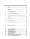
26-3 Correction Control Register Format........................................................................................... 561
26-4 Storing Example to EEPROM (when One Place is Corrected)................................................ 562
26-5 Connecting Example with EEPROM (Using 2-Wire Serial I/O Mode) ..................................... 562
26-6 Initialization Routine ................................................................................................................... 563
26-7 ROM Correction Operation......................................................................................................... 564
26-8 ROM Correction Example........................................................................................................... 565
26-9 Program Transition Diagram (when One Place is Corrected).................................................. 566
26-10 Program Transition Diagram (when Two Places are Corrected) ............................................. 567


